
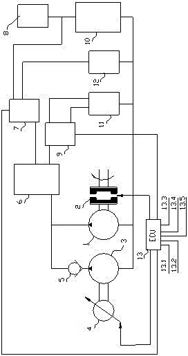
Engine heat management system consisting of controllable water pumps and variable water resistance loop

A thermal management system and circuit composition technology, applied in the cooling of engine components, machines/engines, engines, etc., can solve problems such as inability to adjust coolant flow, high cost, and deterioration of emission levels

Active Publication Date: 2016-08-24
HUNAN OIL PUMP
View PDF4 Cites 9 Cited by
  • Summary
  • Abstract
  • Description
  • Claims
  • Application Information

AI Technical Summary

Problems solved by technology

However, when the internal combustion engine rotates at a high speed, especially in light load conditions, if the coolant flow provided by the water pump is too large, it will take away too much heat, making the internal combustion engine operating temperature lower than the ideal target temperature, so it is necessary to reduce the temperature as much as possible. Coolant flow; in addition, during a cold start of the internal combustion engine, the coolant flow needs to be kept as low as possible in order to shorten the warm-up time, otherwise, a long warm-up time will increase the fuel consumption of the engine and worsen the emission level
[0003] In the prior art, due to the mechanical transmission between the mechanical water pump and the internal combustion engine, as long as the internal combustion engine is running, the mechanical water pump will run, and the speed ratio of the mechanical water pump and the internal combustion engine will form a fixed speed ratio. to adjust the flow of coolant
At present, some companies have begun to develop and even apply electronic water pumps. Electronic water pumps are controlled by electronic control units to achieve separation of coolant flow control and internal combustion engine speed. However, compared with mechanical water pumps, electronic water pumps are more costly and Due to the limitation of motor power, its flow capacity is limited, which cannot meet the requirements of medium and large displacement engines.

Method used


Image

  • Engine heat management system consisting of controllable water pumps and variable water resistance loop

Examples


Embodiment Construction

[0025] In order to facilitate the understanding of those skilled in the art, the present invention will be further described below in conjunction with the embodiments and accompanying drawings, and the contents mentioned in the embodiments are not intended to limit the present invention.

[0026] In the description of the present invention, it should be understood that the terms "first" and "second" are used for description purposes only, and cannot be interpreted as indicating or implying relative importance or implicitly indicating the quantity of indicated technical features. In the description of the present invention, "plurality" means two or more, unless otherwise specifically defined. In the description of the present invention, it should be noted that unless otherwise specified and limited, the terms "installation", "connection" and "connection" should be understood in a broad sense, for example, it can be a mechanical connection or an electrical connection, or it can b...


PUM


Abstract

The invention provides an engine heat management system consisting of controllable water pumps and a variable water resistance loop. The engine heat management system comprises an engine body, an engine ECU, an expansion tank, a main water pump and an auxiliary water pump, wherein the main water pump and the auxiliary water pump are connected in parallel; the main water pump is a switching type water pump and is controlled by an electric control clutch; the auxiliary water pump is an electronic water pump and is controlled by a driving motor; a parallel-connected outlet of the two water pumps is connected to the engine body and then is divided into a cylinder body loop and a cylinder cover loop; the cylinder body loop is connected in series with a first electronic thermostat and a first heat exchange component in sequence; the cylinder cover loop is connected in series with a second electronic thermostat and a second heat exchange component in sequence; the electric control clutch, the driving motor and the electronic thermostats are electrically connected with the engine ECU; the engine ECU is further electrically connected with a plurality of signal detection units. According to the technical scheme, flow adjustment and water resistance adjustment under different working conditions can be realized, so that heat management of an engine cooling system and the power consumption of the water pumps can be in the best fitness.

Description

technical field [0001] The invention relates to the technical field of internal combustion engine cooling systems, in particular to an engine thermal management system composed of a controllable water pump and a variable water resistance circuit. Background technique [0002] The energy saving of internal combustion engine is the hot spot and focus of the research and development of internal combustion engine technology at present, and the cooling system has been widely valued because of its significant energy saving potential for improving engine combustion. According to the principle of the cooling system of the internal combustion engine, when the temperature of the coolant of the internal combustion engine is high, in order to prevent the internal combustion engine from overheating, the cooling water pump must provide a large enough coolant flow. Severe heat dissipation conditions, that is, low speed and full load conditions of the internal combustion engine. However, w...

Claims


Application Information

Patent Timeline
IPC IPC(8): F01P3/02F01P5/10F01P5/12F01P7/16
CPCF01P3/02F01P5/10F01P5/12F01P7/162F01P7/164F01P7/165F01P2003/027F01P2005/105F01P2005/125
Inventor 许仲秋宋善国
Owner HUNAN OIL PUMP
Learn More