Double-cavity hydraulic retarding device integrated at bottom of engine

A technology of retarder and hydraulic retarder, which is applied in the direction of mechanical equipment, brake type, liquid resistance brake, etc., to achieve the effect of improving low-speed performance, rapid warm-up or temperature increase, and small size

Active Publication Date: 2014-01-08
JIANGSU UNIV OF TECH
View PDF5 Cites 3 Cited by
  • Summary
  • Abstract
  • Description
  • Claims
  • Application Information

AI Technical Summary

Problems solved by technology

However, so far, the water-based dual-chamber hydraulic retarder installed at the bottom of the engine has rarely been mentioned.

Method used


Image

  • Double-cavity hydraulic retarding device integrated at bottom of engine
  • Double-cavity hydraulic retarding device integrated at bottom of engine
  • Double-cavity hydraulic retarding device integrated at bottom of engine

Examples


Embodiment Construction

[0026] In order to make the content of the present invention more clearly understood, the present invention will be further described in detail below based on specific embodiments and in conjunction with the accompanying drawings.

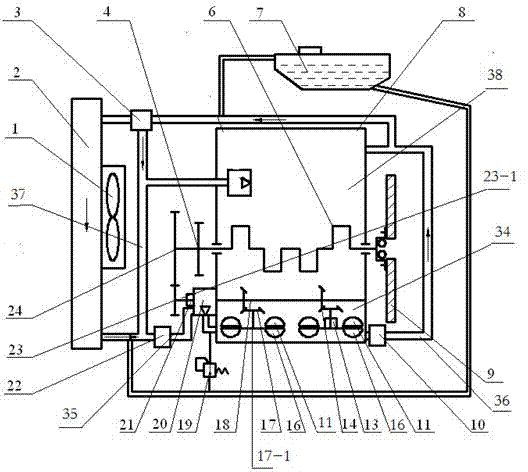
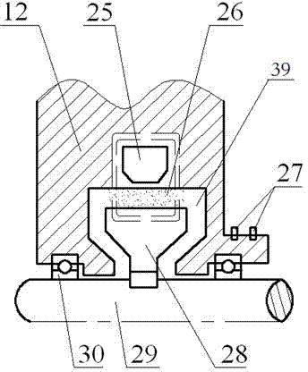
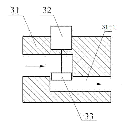
[0027] Such as Figure 1~3 As shown, a dual-chamber hydraulic retarder integrated at the bottom of the engine, including a hydraulic retarder and a control unit, the hydraulic retarder is installed at the bottom of the engine 8, and the hydraulic retarder has retarding work Cavity 34, which also includes centralized output shaft 18, inlet pipe 35, outlet pipe 36, pump 20, return pipe 37 and inlet throttle valve 22 for controlling the flow of coolant in the inlet pipe 35 and controlling the flow of coolant in the outlet pipe 36 A large amount of outlet throttle valve 10, the hydraulic retarder has at least two sets of moving wheel and fixed wheel devices and is arranged in the retarder working chamber 34, each set of moving wheel and fixed wheel ...


PUM


Abstract

The invention discloses a double-cavity hydraulic retarding device integrated at the bottom of an engine. The double-cavity hydraulic retarding device comprises a hydraulic retarder and a control unit, wherein the hydraulic retarder is installed at the bottom of the engine and provided with a retarding working cavity, and the hydraulic retarder further comprises a concentrated output shaft, an inlet pipeline, an outlet pipeline, a pump, a reflux pipeline, an inlet throttle valve and an outlet throttle valve. The hydraulic retarder is provided with two sets of moving wheel and fixed wheel devices which are arranged in the retarding working cavity, and each set of moving wheel and fixed wheel device comprises a moving wheel and a fixed wheel. An engine crankshaft is movably connected with the concentrated output shaft through a first transmission device, a master clutch is arranged between the first transmission device and the concentrated output shaft, and an auxiliary clutch is arranged between the moving wheel of the second set of moving wheel and fixed wheel device and a corresponding second transmission device. The double-cavity hydraulic retarding device takes an engine cooling agent as a working medium and can eliminate no-load loss, improve low-speed performance and provide effective retarding and braking functions.

Description

technical field [0001] The invention relates to a double-cavity hydraulic retarder integrated at the bottom of an engine, which belongs to the technical field of vehicle auxiliary braking. Background technique [0002] When the vehicle is under continuous braking for a long time, high-intensity braking or frequent braking, the temperature of the brake disc or brake drum will increase significantly, resulting in a decrease in the friction factor, aggravated wear, and partial or even complete loss of braking performance. Dangerous thermal recession phenomenon. Although the application of anti-lock brake system (ABS) and electronic brake force distribution system (EBD) has improved the stability and reliability of vehicle braking, they have little effect on the thermal fading phenomenon of brakes. At present, many countries including my country have clearly stipulated that passenger cars and trucks above a certain specification must be equipped with auxiliary braking devic...

Claims


Application Information

Patent Timeline
Patent Type & Authority Applications(China)
IPC IPC(8): F16D57/06
Inventor 王奎洋何仁唐金花许航
Owner JIANGSU UNIV OF TECH
Why Eureka
Try Eureka