Hydraulic buffer device and buffer oil cylinder comprising device

一种液压缓冲、油缸的技术,应用在液压零部件领域,能够解决缓冲质量不够好、零部件缓冲效果影响较大、无法调节等问题

Active Publication Date: 2016-08-24
QINGDAO ACME INNOVATION TECH CO LTD
View PDF30 Cites 27 Cited by
  • Summary
  • Abstract
  • Description
  • Claims
  • Application Information

AI Technical Summary

Problems solved by technology

Although the above technologies have played a certain buffering role and reduced the mechanical collision strength of the oil cylinder to a certain extent, there are still the following deficiencies: 1. The buffering method adopted is relatively simple, and the structural layout is difficult; 2. It is difficult to use the oil return cavity section at the same time The combined method of flow back pressure and high-pressure chamber pressure relief and unloading, the buffer efficiency is not high enough; 3. When the oil return chamber throttles back pressure, the opening of the throttle port is relatively fixed, and the buffering process cannot be adjusted according to the cylinder piston movement speed. The size and change of the buffer are adjusted adaptively, the buffer quality is not good enough, and the controllability of the buffer effect is poor; 4. The manufacturing precision of the buffer mechanism is high, and the wear or eccentricity of the parts has a greater impact on the buffer effect, and even directly Leading to buffer failure and insufficient reliability

Method used


Image

  • Hydraulic buffer device and buffer oil cylinder comprising device
  • Hydraulic buffer device and buffer oil cylinder comprising device
  • Hydraulic buffer device and buffer oil cylinder comprising device

Examples


Embodiment 1

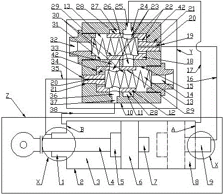
[0097] A buffer cylinder, such as Figure 35-43 As shown, it includes earrings 52, lock pins 53, cylinder head B, cylinder head seat C, cylinder body 2, piston rod 4, piston 6 and cylinder bottom A. It is characterized in that: the buffer cylinder also includes the principle Figure 1-4 The hydraulic shock absorber shown. The buffer device includes an annunciator X and a buffer valve Y, the annunciator X is composed of a signal cavity and a signal plug, and the buffer valve Y is composed of a valve body, a slide valve and a buffer elastic. In order to facilitate understanding and comparison, this embodiment ( Figure 35-43 ) follows the principle Figure 1-4 The part number, the specific structure is detailed as follows.

[0098] The cylinder head C is a ring with a positioning cavity 59 in the center, and the positioning concave hole 60 is coaxially arranged at one end of the positioning cavity 59, and one end of the cylinder body 2 is inserted into the positioning concave h...

Embodiment 2

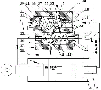
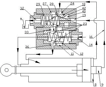
[0110] A buffer cylinder, such as Figure 44-47 As shown, it includes an earring 52, a lock pin 53, a cylinder head B, a cylinder head seat C, a cylinder body 2, a piston rod 4, a piston 6 and a cylinder bottom A. It is characterized in that: the buffer oil cylinder also includes the principle Figure 16-17 The two-way hydraulic shock absorber shown. The buffer device includes an annunciator X and a buffer valve Y, the annunciator X is composed of a signal cavity and a signal plug, and the buffer valve Y is composed of a valve body, a slide valve and a buffer elastic. In order to facilitate understanding and comparison, this embodiment follows the principle Figure 16-17 Compared with Example 1, only the structure of the buffer valve Y has changed, and now only the changed parts are described in detail below, and the rest refer to the foregoing.

[0111] Shock valve Y is equipped with two sets of slide valves, using two spools II12b (see the principle for the specific struc...


PUM


Abstract

The invention discloses a hydraulic buffer device and a buffer oil cylinder comprising the device, belongs to the field of hydraulic parts and overcomes the defects that a buffer mechanism of the buffer oil cylinder in the prior art is complex, high in manufacturing accuracy requirement, difficult in structural arrangement, low in buffer efficiency and reliability, poor in buffer effect controllability and buffer quality, and difficultly employs a composite mode of throttling back pressure of an oil return chamber and pressure-relief unloading of a high pressure chamber at the same time. An annunciator is arranged at a position where an oil cylinder journey approaches to a destination so as to control movement of a slide valve of the buffer device, thus the opening degree and the liquid flow direction of a valve opening of a buffer valve are dynamically regulated, and an oil pressure of an oil cylinder which enters into the oil return chamber is further controlled; a movement velocity of an oil cylinder piston at the destination of the journey is controlled through the modes of the pressure-relief unloading of the high pressure chamber of an oil cylinder and / or the throttling back pressure of the oil return chamber, thus high quality buffer, good buffer controllability and high reliability of the oil cylinder are realized, and the overall quality of a product is improved.

Description

technical field [0001] The invention belongs to the field of hydraulic components, in particular to a hydraulic buffer device and a hydraulic buffer oil cylinder for engineering machinery. Background technique [0002] The hydraulic cylinder is the key executive component of the hydraulic system of construction machinery, which provides power for the working mechanism of construction machinery and completes various operation cycles, such as shoveling operations of loaders and excavation operations of excavators. Due to the requirements of the working conditions of earthwork operations, the oil cylinders of construction machinery generally adopt medium and high pressure heavy-duty oil cylinders. The working pressure is relatively high, and the inertia of the reciprocating parts of the oil cylinder is also large. There is often a large mechanical collision impact between the cylinder head or the cylinder bottom of the fixed part, which leads to oil leakage, cylinder head falli...

Claims


Application Information

Patent Timeline
Patent Type & Authority Applications(China)
IPC IPC(8): F15B15/22F15B13/02
CPCF15B13/025F15B15/22F15B2215/30F15B2211/50518F15B13/02F16F9/512F16F9/19F16F9/466F16F9/46F16F9/346F16F9/464F15B2211/405F15B2211/755F15B15/223
Inventor 朱德伟
Owner QINGDAO ACME INNOVATION TECH CO LTD
Why Eureka
Try Eureka