Inflation and deflation control valve

A technology of inflation and deflation control and deflation valve, which is applied in safety valves, balance valves, valve devices, etc., can solve problems such as high R&D and production costs, small effective diameter of solenoid valves, and increased difficulty in layout, etc., to reduce The effect of application cost, large effective diameter and fast deflation speed

Inactive Publication Date: 2016-08-24
CHONGQING YANZHAO AUTOMOBILE TECH
View PDF0 Cites 3 Cited by
  • Summary
  • Abstract
  • Description
  • Claims
  • Application Information

AI Technical Summary

Problems solved by technology

The parts should be scattered on the car body, which is not only complicated, but also the cost of research and development and production is high; at the same time, due to the small effective diameter of the solenoid valve, the solenoid valve forms a throttling effect during the deflation process, which greatly slows down the air flow. The deflation speed of the tire is improved; for the existing technical level, it is difficult to increase the effective diameter of the solenoid valve without excessively increasing the volume and power consumption, and it is usually improved by adding other auxiliary valves. deflation rate, which in turn makes the system overly complex and less reliable, making it more difficult to deploy on the vehicle

Method used


Image

  • Inflation and deflation control valve

Examples


Embodiment Construction

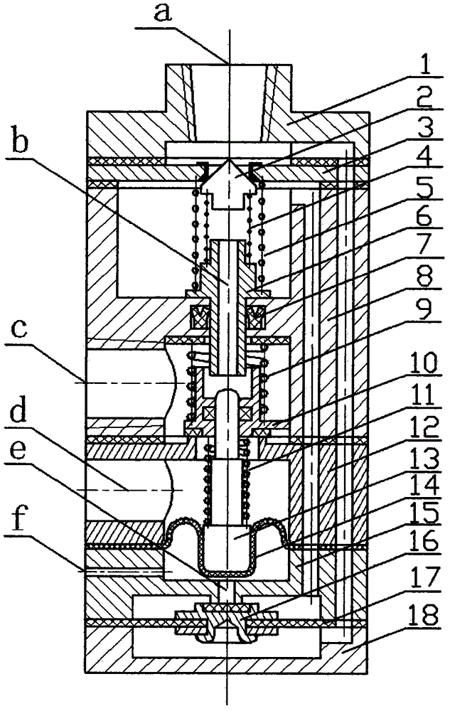
[0027] The present invention will be further described below in conjunction with the accompanying drawings.

[0028] The inflation and deflation control valve of the present invention is as figure 1As shown, the valve cover (1), the first valve seat (3), the main valve body (8), the second valve seat (12), the first diaphragm (14), and the Three valve seats (15), second diaphragm (17), valve bottom (18) and coaxially installed one-way valve core (2), inflation valve core (6), deflation valve core (10), valve stem (13), the pilot spool (16), the first return spring (4), the second return spring (5), the third return spring (9) and the fourth return spring (11) and sealing gaskets and other components. Between the valve cover (1) and the first valve seat (3), between the first valve seat (3) and the main valve body (8) and between the main valve body (8) and the second valve seat (3) Sealing gaskets are provided; the valve cover (1) is provided with a first air circuit interfa...


PUM


Abstract

The invention discloses an inflation and deflation control valve. The inflation and deflation control valve mainly consists of a valve deck, a first valve seat, a main valve body, a second valve seat, a first diaphragm, a third valve seat, a second diaphragm and a valve bottom which are sequentially arranged from top to bottom as well as a check valve element, an inflation valve element, a deflation valve element, a valve rod, a pilot valve element, four reset springs and other components which are coaxially arranged; a first gas path connection port is formed in the valve deck; the upper cavity of the main valve body communicates with the lower cavity of the valve body through the inflation valve element; the check valve element is arranged in the upper cavity of the main valve body and forms a sealing pair with the first valve base; the deflation valve element is located in the lower cavity of the main valve body and forms a sealing pair with the second valve base; the pilot valve element is arranged on the second diaphragm and forms a sealing pair with the third valve base; an exhaust port is formed in the second valve base; a second gas path connection port is formed in the main valve body; a throttling exhaust hole is formed in the third valve base; and a first gas path and a second gas path are arranged on the valve body. The inflation and deflation control valve has the beneficial effects that the effective through diameter of a deflation valve opening is large, so that deflation speed is high; the automation degree is high; application cost is low.

Description

technical field [0001] The invention relates to a valve assembly in a tire central inflation and deflation system, in particular to an inflation and deflation control valve capable of automatically performing the functions of inflation, deflation and pressure maintenance. Background technique [0002] Military vehicles and off-road vehicles often drive in areas with complex road conditions. When the above-mentioned vehicles pass through soft roads such as deserts, river beaches, and swamps, it is necessary to deflate the tires to increase the contact area between the tires and the ground, thereby enhancing the tires. Can pass through smoothly, when above-mentioned vehicle enters good road condition, to keep its good mobility to tire inflation again. Military off-road vehicles are often responsible for special tasks such as the transportation of weapons and personnel, the maneuvering of weapon systems and communication command systems, and field rescue. It is necessary to use...

Claims


Application Information

Patent Timeline
Patent Type & Authority Applications(China)
IPC IPC(8): F16K17/00
Inventor 刘艳昭
Owner CHONGQING YANZHAO AUTOMOBILE TECH
Why Eureka
Try Eureka