
Method for detecting coplanarity of eight spliced mirrors

A coplanar and mirror frame technology, which is applied to measuring devices, instruments, and optical devices, can solve problems such as the inability to process single reflectors and limited surface accuracy requirements, so as to reduce the cycle time and increase the speed of assembly and adjustment. , Improve the effect of detection accuracy

Active Publication Date: 2022-07-12
INST OF OPTICS & ELECTRONICS - CHINESE ACAD OF SCI
View PDF7 Cites 0 Cited by
  • Summary
  • Abstract
  • Description
  • Claims
  • Application Information

AI Technical Summary

Problems solved by technology

At the same time, limited by the surface accuracy requirements, it will not be possible to process a single mirror with a caliber of 24m in the future

Method used


Image

  • Method for detecting coplanarity of eight spliced mirrors
  • Method for detecting coplanarity of eight spliced mirrors
  • Method for detecting coplanarity of eight spliced mirrors

Examples


Embodiment Construction

[0024] The present invention will be further described below with reference to the accompanying drawings and specific embodiments.

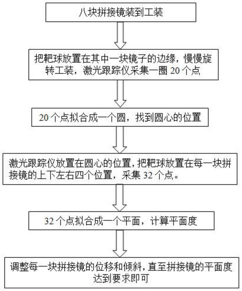
[0025] A method for detecting the coplanarity of eight splicing mirrors in this embodiment is implemented according to the following steps:

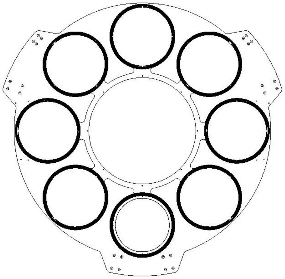
[0026] Step 1, put the eight splicing mirrors according to the figure 2 The mirror frame of the eight splicing mirrors installed in the tooling is shown, and the tooling supports a circular ring. The mirror frames of the eight splicing mirrors are evenly distributed on the tooling, and the frame of each splicing mirror can be adjusted in five dimensions;

[0027] Among them, each splicing mirror on the tooling is a circular mirror with a diameter of 390mm, and its mirror frame is evenly distributed on the ring.

[0028] Among them, eight splicing mirrors are figure 2 The position diagram is installed on the tooling. The tooling and the splicing mirror are installed on the rotating platform. The frame of...


PUM


Abstract

The invention discloses a method for detecting the coplanarity of eight spliced mirrors, and the method carries out the installation and adjustment of the eight spliced mirrors through a laser tracker, and enables the flatness of the eight spliced mirrors to meet the requirements. Firstly, eight spliced mirrors are installed in a tool, the center of the tool and the center of a rotating platform are adjusted to be consistent through a laser tracker, the laser tracker is placed at the center position, then target balls are placed at the upper position, the lower position, the left position and the right position of each spliced mirror, 32 points are collected and fitted into a plane, and the flatness is calculated. And according to the coordinates of the points, the displacement and inclination of each spliced mirror are adjusted until the flatness of the spliced mirror meets the requirement. According to the invention, the problems of assembling and detecting eight spliced mirrors are solved.

Description

technical field [0001] The invention belongs to the field of wavefront detection, in particular to a method for detecting the coplanarity of eight splicing mirrors. Background technique [0002] Based on the traditional single reflective optical system, facing subversive problems such as weight, volume, tolerance, etc., it is almost impossible to achieve 1m resolution on the stationary orbit. It is estimated that to achieve 1m resolution imaging on the ground in static orbit, a giant aperture optical system is required, that is, the optical aperture is about 24m and the weight is hundreds of tons, far exceeding the launch capacity of the launch vehicle. At the same time, limited by the surface shape accuracy requirements, it is impossible to process a single mirror with a diameter of 24m in the future. From the end of the 20th century, foreign countries began to develop new optical imaging technologies to solve a series of problems faced by large-aperture optical imaging sy...

Claims


Application Information

Patent Timeline
IPC IPC(8): G01B11/30G01B11/00
CPCG01B11/30G01B11/002
Inventor 罗倩邵俊铭吴时彬杜俊峰高国涵
Owner INST OF OPTICS & ELECTRONICS - CHINESE ACAD OF SCI
Learn More