

Far-infrared camera lens, lens unit, and imaging apparatus
a technology of infrared camera and lens unit, which is applied in the field of infrared camera lens, can solve the problems that the wide-angle lens cannot be obtained by one lens and two lenses, and achieve the effect of effectively using the refractive power of the third lens
- Summary
- Abstract
- Description
- Claims
- Application Information
AI Technical Summary
Benefits of technology
Problems solved by technology
Method used
Image

Examples
first embodiment
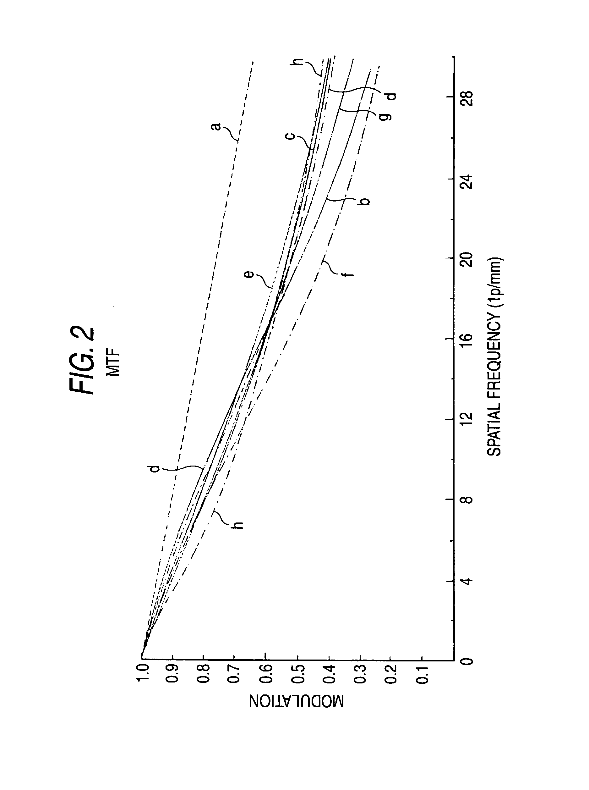
FIGS. 1 and 2
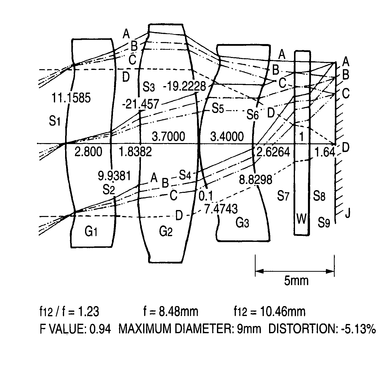
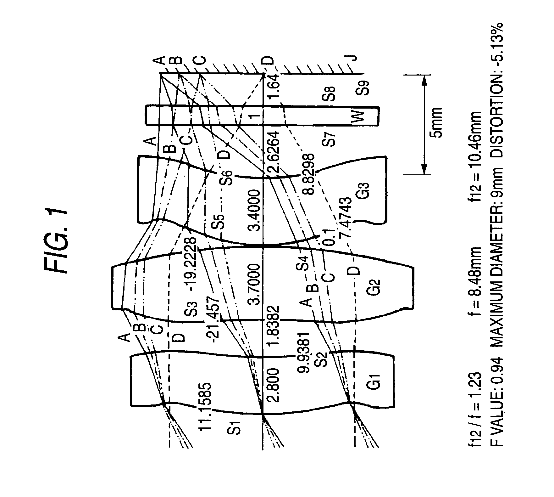
[0077]ZnS, a set of three lenses (G1, G2, G3)
[0078]f12 / f=1.23
[0079]f=8.48 mm
[0080]f12=10.46 mm
[0081]F value 0.94
[0082]Maximum diameter 9 mm
[0083]distortion −5.13%
[0084]Viewing angle 64.2°
[0085]In a first embodiment, a viewing angle is 64.2° and f12 / f is 1.23. f12 is a composite focal distance of G1 and G2, and f is a total focal distance. Although an explanation has been already made repeatedly, the focal distance f cannot be defined as a whole because the lenses are aspheric lenses. The focal distance f is a value defined for a light beam passing along the locus near a central axis. The same is true for f12. The F value of a lens is f / D obtained by dividing the focal distance f by an effective diameter D.
[0086]FIG. 1 illustrates a cross section of a lens system according to the first embodiment. This is configured to include three lenses. The three lenses are set to G1, G2, and G3 from an object side. The three lenses are all formed of ZnS. A powder material of ZnS is ...
second embodiment
FIGS. 3 and 4
[0160]ZnS, a set of three lenses (G4, G5, G6)
[0161]f12 / f=1.59
[0162]f=8.49 mm
[0163]f12=13.5 mm
[0164]F value 0.94
[0165]Maximum diameter 9 mm
[0166]Distortion −4.38%
[0167]Viewing angle 64.22°
[0168]In the second embodiment, a viewing angle is 64.22°, which is a sufficiently wide angle. In order to obtain a wide angle, f is 8.49 mm which is short. When D is calculated from the previous expression D=2 ftan (Y / 2), D=10.65 mm, but the sensor diameter is 10 mm which is slightly insufficient. However, from a point of view of an MTF, the MTF is 0.2 or more even in a case of a light beam having an incidence angle of 32.11°. Accordingly, the viewing angle 64.22° is sufficient.
[0169]FIG. 3 illustrates a cross section of a lens system according to the second embodiment. This lens system is also configured to include three lenses G4, G5, and G6 and is formed of ZnS. A flat member corresponding to a fourth sheet is a window W of a sensor. The sensor window is provided in a sensor and is ...
third embodiment
FIGS. 5 and 6
[0197]ZnS, a set of three lenses (G7, G8, G9)
[0198]f12 / f=0.91
[0199]f=7.68 mm
[0200]f12=7 mm
[0201]F value 1.06
[0202]Maximum diameter 7.2 mm
[0203]Distortion −5.8%
[0204]Viewing angle 68.90°
[0205]In the third embodiment, a viewing angle is 68.90°, which is a sufficiently wide angle. In order to obtain a wide angle, f12 is 7 mm which is short. f is 7.68 mm which is also short. Since f12 / f=0.91, the value falls within a range of 0.9 to 1.6 requested in the invention. Since the F value is 1.06, it is a sufficiently bright lens. Referring to the above-described expression of D=2 ftan(Y / 2), 2 ftan 34.45°=10.5 mm. Since the effective dimension D of a sensor is 10 mm but f, which is effective for ambient light, is shorter than 7.68 mm, light corresponding to Θ=34.45° can be successfully formed on an end of an image surface.
[0206]FIG. 5 illustrates a cross section of a lens system according to the third embodiment. This lens system is also configured to include three lenses G7, G8, ...
PUM
| Property | Measurement | Unit |
|---|---|---|
| viewing angle | aaaaa | aaaaa |
| distance | aaaaa | aaaaa |
| focal distance f12 | aaaaa | aaaaa |
Abstract
Description
Claims
Application Information