Coating machine and coating method

A coating machine and mechanical pump technology, applied in the field of liquid crystal display processing, can solve the problems of low fragmentation rate of TFT liquid crystal display screen, high impact force of the display screen, etc., to improve processing yield, reduce fragmentation rate and control effect Good results

Active Publication Date: 2018-03-27
JIANGXI HOLITECH TECH
View PDF8 Cites 0 Cited by
  • Summary
  • Abstract
  • Description
  • Claims
  • Application Information

AI Technical Summary

Problems solved by technology

[0002] The vacuum coating machine is used to coat liquid crystal display screens. There are multiple cavities connected in sequence and main vacuum tubes connected to the cavities in the coating machine. The cavities are connected to the main vacuum tubes through straight tubes, and the straight tubes are equipped with valves. , the first cavity and the last cavity are respectively connected with the outside atmosphere. When the first cavity of the existing coating machine is pumped from atmospheric pressure to vacuum, the pumping time is only about 20s, and the pumping speed is relatively f

Method used


Image

  • Coating machine and coating method
  • Coating machine and coating method

Examples


Embodiment Construction

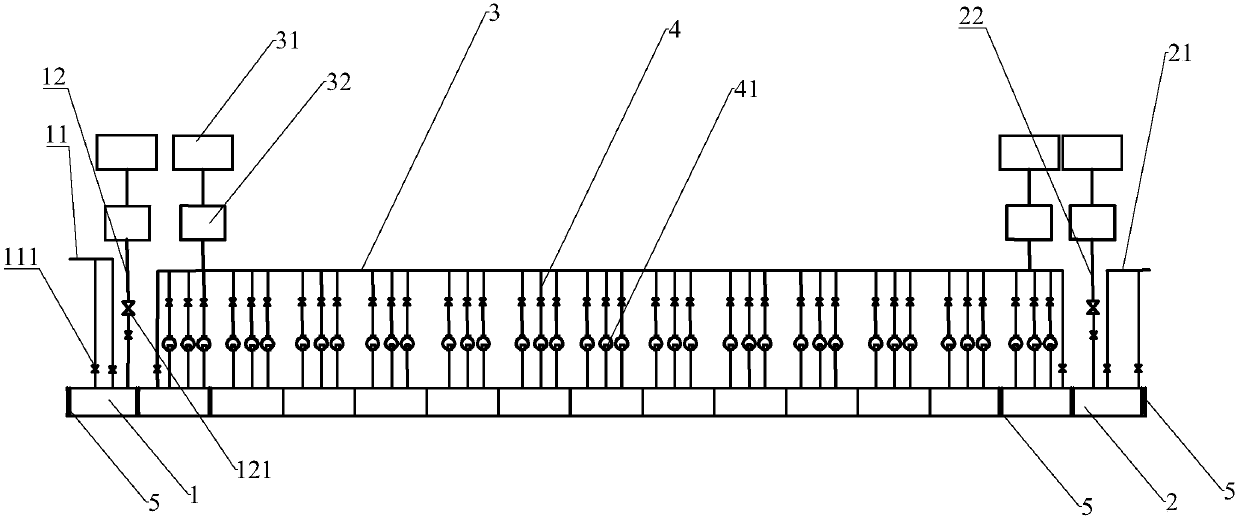
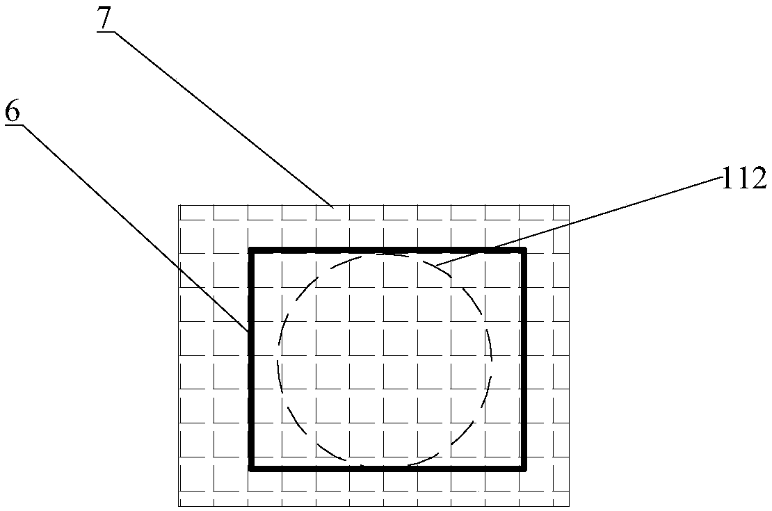
[0021] Such as figure 1 , figure 2 As shown, a coating machine includes a plurality of sequentially connected cavities, the cavities include M1, M2, M3...M13, M14, M15 cavities, M1, M15 cavities are low vacuum cavities, M2, M14 cavities It is a transition chamber with a vacuum degree of 10 -4 Pa, M3 to M13 are high vacuum chambers. The M1 cavity 1 is provided with an air outlet pipe 11 and a first vacuum pipe 12, and the M15 cavity 2 is provided with an air inlet pipe 21 and a second vacuum pipe 22. The ends of the air outlet pipe 11 and the air inlet pipe 21 are respectively connected to the atmosphere. , The body of the intake pipe 21 is provided with at least one vacuum valve 111, and the first vacuum pipe 12 and the second vacuum pipe 22 are respectively provided with a mechanical pump 31, a Luoqi pump 32, and a butterfly valve 121; The air outlet 112 connected to the air outlet pipe 11 is provided with a first filter screen 7 on the air outlet 112, and a baffle 6 is also...


PUM


Abstract

The invention provides a coating machine and a coating method. The piece breaking rate caused when a coating machine is used for producing TFT liquid crystal display screens can be reduced, and the machining yield of the TFT liquid crystal display screen can be improved.

Description

Technical field [0001] The invention relates to the technical field of liquid crystal display processing, in particular to a coating machine and a coating method. Background technique [0002] The vacuum coating machine is used to coat the liquid crystal display screen. The coating machine is equipped with a plurality of successively connected cavities and a main vacuum tube connected to the cavity. The cavity is connected to the main vacuum tube through a straight tube, and the straight tube is equipped with a valve , The first cavity and the last cavity are respectively connected to the outside atmosphere. When the first cavity of the existing coating machine is pumped from atmospheric pressure to vacuum, the pumping time is only about 20s, and the pumping speed is faster. When the last cavity is deflated from vacuum to atmospheric pressure, the deflation time is only about 10s, and the deflation speed is relatively fast, but the pumping speed and deflation speed are too fast, ...

Claims


Application Information

Patent Timeline
IPC IPC(8): C23C14/56C23C14/54
CPCC23C14/54C23C14/56
Inventor 郭友根
Owner JIANGXI HOLITECH TECH
Why Eureka
Try Eureka