
Anti-Multipath Scattering Detection Method for Radar with Single Transmitter and Three Receiver Antennas

A detection method and anti-multipath technology, applied in radio wave measurement systems, radio wave reflection/reradiation, measurement devices, etc., can solve problems such as difficult engineering implementation, high cost, and immature technology, and achieve radar detection Good performance, strong engineering applicability, and high detection probability

Active Publication Date: 2018-01-09
NAT UNIV OF DEFENSE TECH
View PDF7 Cites 0 Cited by
  • Summary
  • Abstract
  • Description
  • Claims
  • Application Information

AI Technical Summary

Problems solved by technology

However, the selection of multiple frequencies needs to be adaptively selected through algorithm design, which means that the operating frequency of the radar will change with the change of the working scene, which has high requirements for the radar transmitter, and the engineering implementation is difficult and costly
MIMO radar uses space diversity theory to eliminate the adverse effects of multipath scattering on radar target detection. However, MIMO radar is still in the stage of development and experimentation, and there is still a long way to go before it is practical in engineering.
In addition, polarization diversity system radar can also improve radar target detection performance under multipath conditions, but its improvement effect is limited, and the cost of radar engineering implementation is too high
In summary, the new system radar can improve the performance of radar target detection under multipath conditions, but the cost is greatly increased, and the technology is not yet mature. Currently, there is no practical radar anti-multipath scattering detection method

Method used


Image

  • Anti-Multipath Scattering Detection Method for Radar with Single Transmitter and Three Receiver Antennas
  • Anti-Multipath Scattering Detection Method for Radar with Single Transmitter and Three Receiver Antennas
  • Anti-Multipath Scattering Detection Method for Radar with Single Transmitter and Three Receiver Antennas

Examples


Embodiment Construction

[0040] Embodiments of the present invention will be further described below in conjunction with the accompanying drawings.

[0041] The present invention provides a single-transmission and three-reception antenna radar anti-multipath scattering detection method, comprising the following steps:

[0042] The first step is to select three antenna erection heights

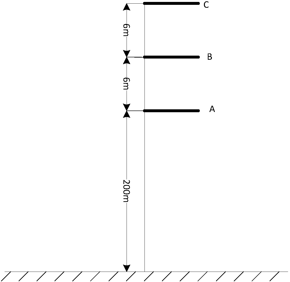
[0043] The height of the transmitting / receiving antenna A is selected as 200m, and the transmitting / receiving antenna A has both transmitting and receiving functions, and the transmitting and receiving are carried out in time-sharing. Another selection of receiving antenna B and receiving antenna C, the heights are 206m and 212m. The transmitting / receiving antenna A, the receiving antenna B and the receiving antenna C are all in the same vertical plane.

[0044] The second step is to calculate the test statistics

[0045] The signals received by the i-th receiving antenna of the radar can be expressed as

[0046] ...


PUM


Abstract

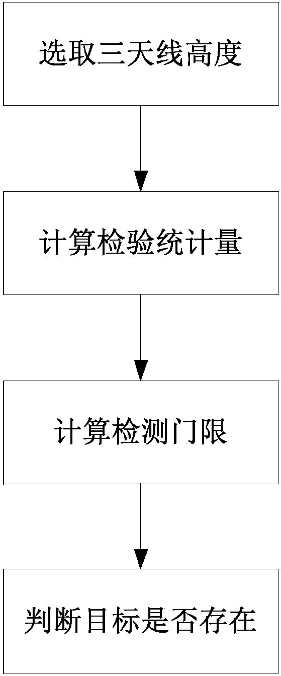
The invention discloses a single-emission tri-reception antenna radar anti-multipath scattering detection method. The method includes four steps of firstly selecting erect height of three antennas, secondly calculating the examination statistical magnitude according to the signals received by three reception antennas, thirdly calculating a detection threshold, and fourthly determining the existence of a target. A space diversity theory is used, a radar employs a means of single-emission tri-reception antennas to obtain observation signals under multipath conditions, and the target detection is realized with the maximum value of the absolute value of the difference of reception antenna echo power in pairs as the examination statistical magnitude to improve the radar target detection performance under anti-multipath conditions. The radar target detection performance under anti-multipath conditions is improved substantially. No modification for a radar transmitter is required, and only two reception antennas and two-path reception channels are additionally installed. Realization is easy, and the engineering applicability is high.

Description

【Technical field】 [0001] The invention relates to a radar detection technology, in particular to a radar anti-multipath scattering detection method, more specifically to a single-transmission and three-reception antenna radar anti-multipath scattering detection method. 【Background technique】 [0002] Radar has multipath scattering when detecting low-altitude targets. Under the condition of multi-path scattering, the target echo reflected by the ground sea surface and the target direct wave are in the same radar range resolution unit, and the multi-channel signals are superimposed on each other, resulting in interference effect, which causes the target echo received by the radar to sometimes strengthen and sometimes attenuate. This has a serious impact on radar target detection. Therefore, it is of great military application value to study radar anti-multipath scattering detection methods and improve radar low-altitude target detection performance. [0003] At present, expe...

Claims


Application Information

Patent Timeline
Patent Type & Authority Patents(China)
IPC IPC(8): G01S7/42G01S7/02G01S13/04
CPCG01S7/023G01S7/42G01S13/04
Inventor 杨勇肖顺平冯德军张文明
Owner NAT UNIV OF DEFENSE TECH
Learn More