Special optical fiber sensing cable
A technology of optical fiber sensing and optical cable, which is applied in the direction of fiber mechanical structure, etc., can solve the problems of poor mechanical stability, output waste products, error-prone wiring, etc., and achieve the effect of stable structure and high consistency
- Summary
- Abstract
- Description
- Claims
- Application Information
AI Technical Summary
Problems solved by technology
Method used
Image
Examples
Embodiment 1
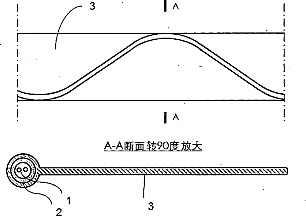
[0032] figure 1 It is a structural diagram of Embodiment 1 of the present invention.
[0033] The optical fiber 1 has a coating with an outer diameter of 250 microns, the tensile element 2 is a stainless steel tube with an outer diameter of 2.5mm, and the optical fiber 1 is built in and filled with oil; the belt body 3 is made of polyvinyl chloride.
[0034] The belt body 3 has a width of 50 mm and a thickness of 1.0 mm; the tensile element 2 is S-shaped, consisting of arcs and straight segments with a bending radius of 50 mm and a pitch of 180 mm.
[0035] During the manufacturing process of the optical cable, the tensile element 2 with the built-in optical fiber 1 is firstly bent into an S-shape mechanically, and then the tape body 3 is added by a thermoplastic process. In this way, it can be ensured that the tensile element 2 has no prestress and the belt surface is flat.
[0036] It can be seen from the above structure that the strip body 3 has a light and thin structure...
Embodiment 2
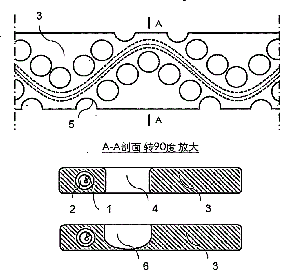
[0039] figure 2 It is a structural diagram of Embodiment 2 of the present invention.
[0040] The optical fiber 1 and the tensile element 2 have an S-shaped curve and are arranged inside the belt body 3; on the belt body 3, a stress relief hole 4 and a stress relief groove 5 are opened around the optical fiber 1 and the tensile element 2.
[0041] The S-shaped curve of the optical fiber 1 and the tensile element 2 can be selected from double circular arcs, sinusoidal curves, and B-spline curves, and can be selected according to the width requirements of the S-shaped curve, the allowable minimum bending radius of the optical fiber 1, and the excess length ratio requirements .
[0042] The allowable minimum bending radius of the optical fiber 1 is mainly determined by the bending resistance performance of the optical fiber 1 itself and the total loss requirement. In long-distance (several kilometers to tens of kilometers) detection, the total loss must be strictly controlled....
Embodiment 3
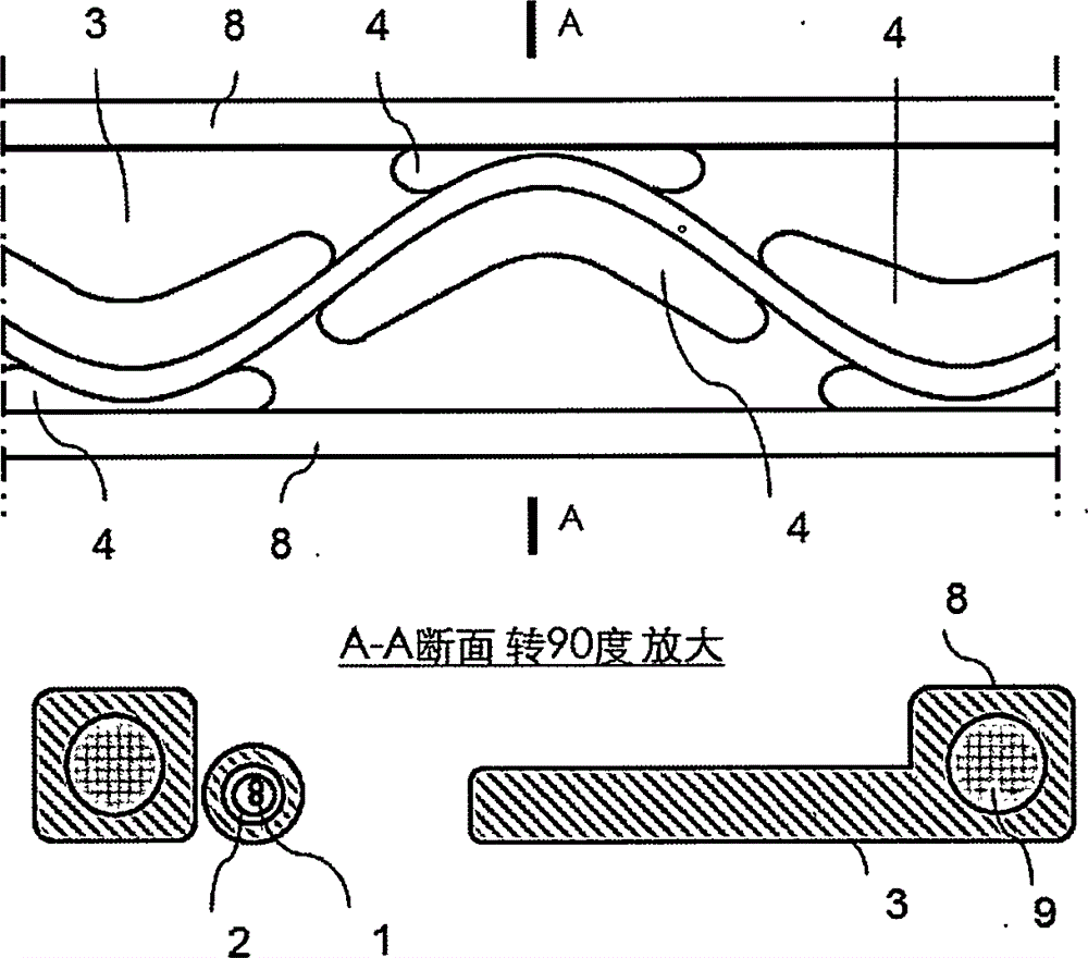
[0062] image 3 It is a structural diagram of Embodiment 3 of the present invention.
[0063] The optical fiber 1 and the tensile element 2 are S-shaped curves and are arranged inside the belt body 3; on the belt body 3, there are stress release holes 4 around the optical fiber 1 and the tensile element 2; Press bump 8.
[0064] It can be seen from the above structure that the anti-compression protrusion 8 can prevent the structure in the middle of the belt body 3 from being stressed, and the stress relief hole 4 arranged between the anti-compression protrusion 8 and the S-shaped curve is beneficial to the optical fiber 1 and the tension-resistant The movement of the element 2, during installation and use, the optical fiber 1 is not subject to tension, torsion or pressure.
[0065] The selection of materials and structures can refer to Example 2.
[0066] Optionally, a reinforcing element 9 is provided within the compression-resistant projection 8 .
[0067] A specific sol...
PUM
 Abstract
Description
Claims
Application Information
 - R&D Engineer
- R&D Manager
- IP Professional
- Industry Leading Data Capabilities
- Powerful AI technology
- Patent DNA Extraction
Browse by: Latest US Patents, China's latest patents, Technical Efficacy Thesaurus, Application Domain, Technology Topic, Popular Technical Reports.
© 2024 PatSnap. All rights reserved.Legal|Privacy policy|Modern Slavery Act Transparency Statement|Sitemap|About US| Contact US: help@patsnap.com


