
An all-fiber lossless cascaded pulse stretcher

A lossless, cascading technology, applied in the laser field, can solve the problems of limited pulse stretch, inability to realize ultra-large dispersion pulse stretcher, large loss, etc., to reduce manufacturing process requirements, improve reproducibility and yield , the effect of increasing the amount of broadening

Active Publication Date: 2019-06-18
WUHAN YANGTZE SOTON LASER CO LTD
View PDF7 Cites 0 Cited by
  • Summary
  • Abstract
  • Description
  • Claims
  • Application Information

AI Technical Summary

Problems solved by technology

[0003] Chirped Fiber Bragg Grating (Chirped Fiber Bragg Grating, CFBG) is a commonly used pulse stretcher in chirped pulse amplifiers. Dispersion), can set the spectral reflectance and reflection curve, usually used together with fiber optic circulator, is widely used in the field of optical fiber communication and sensor; its disadvantage is that due to the limitation of the manufacturing process, it will generate a large loss, and additionally introduce The loss of the fiber optic circulator; another disadvantage is that the amount of pulse stretching is limited, and it is impossible to realize a pulse stretcher based on CFBG with a large amount of dispersion

Method used


Image

  • An all-fiber lossless cascaded pulse stretcher
  • An all-fiber lossless cascaded pulse stretcher
  • An all-fiber lossless cascaded pulse stretcher

Examples


Embodiment 1

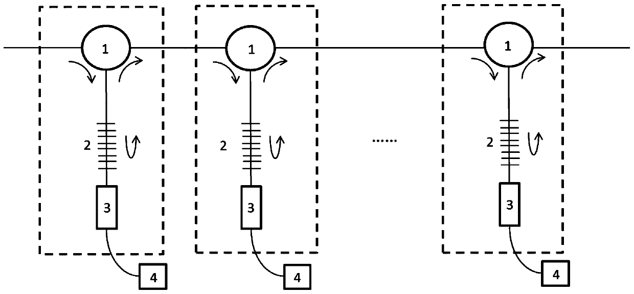
[0034] figure 1 It is a structural schematic diagram of the all-fiber lossless cascaded pulse stretcher provided in this embodiment, as figure 1 As shown, it includes several first units connected in a cascaded manner, and pumping sources 4 corresponding to the number of the first units,

[0035] The first unit includes a fiber circulator 1, a rare earth-doped fiber CFBG 2 and a wavelength division multiplexer 3, the first end of the fiber circulator 1 in the first unit is used to receive pulse signal light, and the second end is connected to the doped fiber The first end of the rare earth fiber CFBG 2 is connected, the second end of the rare earth doped fiber CFBG 2 is connected with the first end of the wavelength division multiplexer 3, and the third end of the optical fiber circulator 1 is connected with the optical fiber ring in the next first unit The first end of the device 1 is connected, and the third end of the last first unit is used as the output end of the pulse ...

Embodiment 2

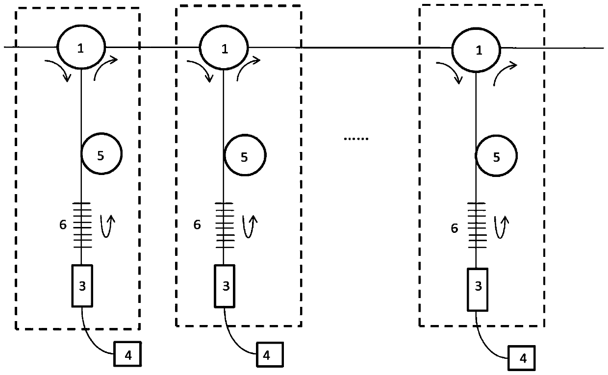
[0041] figure 2 It is a structural schematic diagram of the all-fiber lossless cascaded pulse stretcher provided in this embodiment, as figure 2 As shown, it includes several first units connected in a cascaded manner, and pumping sources 4 corresponding to the number of the first units,

[0042] The first unit includes a fiber optic circulator 1, a passive fiber CFBG 5, a rare earth-doped fiber 6 and a wavelength division multiplexer 3, and the first end of the fiber optic circulator 1 in the first first unit is used to receive pulse signal light, which The second end is connected with the first end of the passive fiber CFBG 5, the second end of the passive fiber CFBG 5 is connected with the first end of the rare earth-doped fiber 6, and the second end of the rare-earth fiber 6 is connected with the first end of the wavelength division multiplexer 3 One end is connected, the third end of the optical fiber circulator 1 is connected with the first end of the optical fiber ci...

Embodiment 3

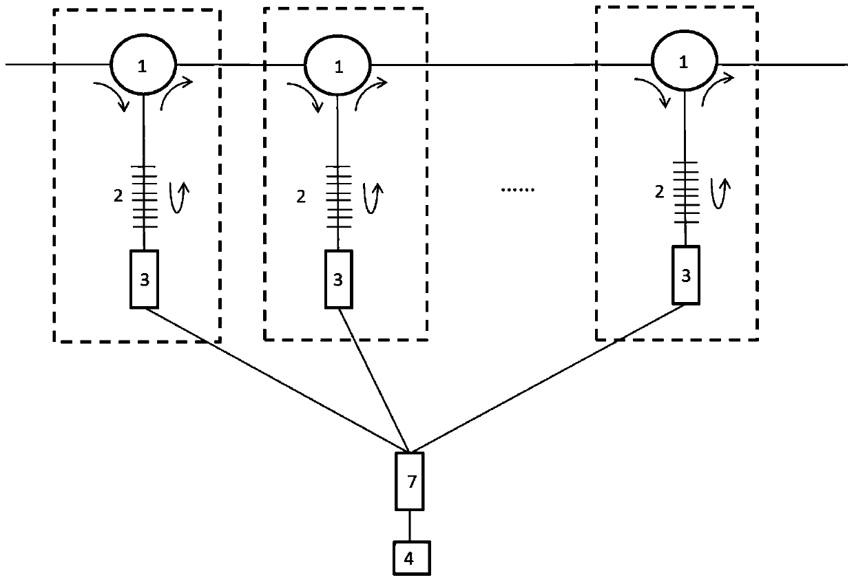
[0047] image 3 It is a structural schematic diagram of the all-fiber lossless cascaded pulse stretcher provided in this embodiment, as image 3 As shown, it includes a pump source 4, an optical fiber splitter 7 and several first units connected in a cascaded manner;

[0048] The first unit includes fiber optic circulator 1, rare earth-doped fiber CFBG 2 and wavelength division multiplexer 3, the first end of fiber optic circulator 1 in the first unit is used for receiving pulse signal light, and its second end is connected with rare earth fiber The first end of CFBG 2 is connected, the second end of rare earth-doped fiber CFBG 2 is connected with the first end of wavelength division multiplexer 3, and the third end of optical fiber circulator 1 is connected with optical fiber circulator 1 in the next first unit The first end of the first unit is connected, and the third end of the last first unit is used as the output end of the pulse signal light; the second end of the wave...


PUM


Abstract

The invention discloses an all-fiber no-loss cascade pulse stretcher. The all-fiber no-loss cascade pulse stretcher comprises at least one pump source, and a plurality of first units; each first unitcomprises an optical fiber circulator, a first widening module and a wavelength division multiplexer; the first end of the optical fiber circulator is used for receiving externally input pulse signallight while the second end is connected with the first end of the first widening module; the second end of the first widening module is connected with the first end of the wavelength division multiplexer; the second end of the wavelength division multiplexer is connected with the output end of the pump source; the third end of the optical fiber circulator is connected with the first end of the optical fiber circulator in the adjacent first unit; the third end of the optical fiber circulator in the last first unit is used as the output end of the pulse signal light; and the multiple first unitsare connected in a cascading manner to form a cascade structure. By virtue of the all-fiber no-loss cascade pulse stretcher, the dispersion measure requirement of a single CFBG can be distributed into multiple CFBGs to be realized in an overlaid manner, and the pulse signal light is amplified to compensate device loss, so that the widening amount can be infinitely increased in a no-loss condition.

Description

technical field [0001] The invention belongs to the field of laser technology, and more specifically relates to an all-fiber lossless cascaded pulse stretcher. Background technique [0002] A chirped pulse amplifier is a commonly used device for amplifying ultrashort (picosecond or femtosecond) pulses. Its principle is to first broaden the ultrashort pulse from the time domain, amplify it, and then compress it back to the ultrashort pulse. Since the peak power of the pulse after stretching is greatly reduced, it is especially suitable for use in optical fiber amplifiers with limited peak power. [0003] Chirped Fiber Bragg Grating (Chirped Fiber Bragg Grating, CFBG) is a commonly used pulse stretcher in chirped pulse amplifiers. Dispersion), can set the spectral reflectance and reflection curve, usually used together with fiber optic circulator, is widely used in the field of optical fiber communication and sensor; its disadvantage is that due to the limitation of the manuf...

Claims


Application Information

Patent Timeline
Patent Type & Authority Patents(China)
IPC IPC(8): H01S3/00H01S3/067G02F1/39
CPCG02F1/39H01S3/0057H01S3/06716H01S3/06725H01S3/0675
Inventor 何飞陈抗抗
Owner WUHAN YANGTZE SOTON LASER CO LTD
Learn More