Shock absorber capable of improving generating efficiency by using suspension magnets under shock absorption working condition

A technology of working state and power generation efficiency, applied in the direction of springs/shock absorbers, electrical components, electromechanical devices, etc. question

Inactive Publication Date: 2012-02-15
李敏
View PDF5 Cites 8 Cited by
  • Summary
  • Abstract
  • Description
  • Claims
  • Application Information

AI Technical Summary

Problems solved by technology

The disadvantage is that the weight of the shock absorber is too large, the cross section of the shock absorber is also too large, it consumes a lot of materials, the cost is high and it lacks practicality.
If a group of NdFeB magnets with a diameter of 3.0 cm are used as the elastic part of the shock absorber of an electric bicycle, the stroke of the shock absorber is only 2.0-3.0 cm; if a group of ferrite magnets with a diameter of 10.0 cm are used as The elastic part of the shock absorber of the electric bicycle, the stroke of the shock absorber is only 2.0-4.0 cm, not only the volume is large, the weight is heavy, the cost is high, the stroke is also too short, there is no flexibility of damping
[0003] In order to overcome the lack of magnetic force of permanent magnets, some people use electromagnets as elastic parts of shock absorbers to increase the magnetic force. The shock absorption effect of the shock absorber changes with the electric energy of the battery, that is, the shock absorption effect of the shock absorber is unstable
In order to prevent the battery from failing to supply power, an additional spring is required as a spare part. This kind of shock absorber has a complicated structure and poor stability.

Method used


Image

  • Shock absorber capable of improving generating efficiency by using suspension magnets under shock absorption working condition
  • Shock absorber capable of improving generating efficiency by using suspension magnets under shock absorption working condition

Examples


Embodiment 1

[0037] Embodiment 1, the shock absorber that can improve the power generation efficiency with the levitation magnet in the shock absorbing working state

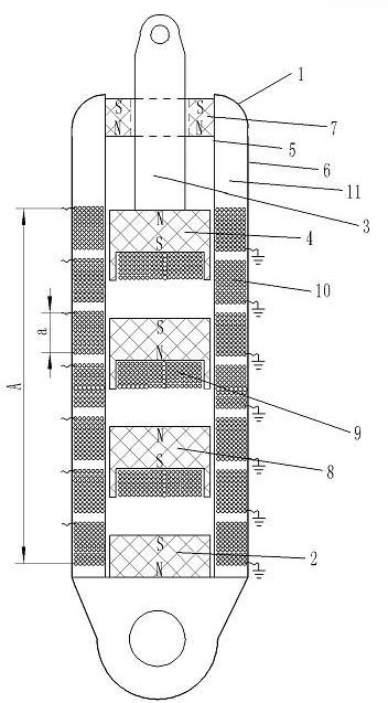
[0038] Such as figure 1 , the inner layer uses a non-magnetic stainless steel tube with an inner diameter of 1.0 cm as the non-magnetic inner tube 5, and a steel tube mainly used to bear the weight is used as a steel load-bearing tube 6 on the outside, and two tubes that are nested inside and outside are used as a shock absorber The tube body 1. The positioning permanent magnet 2 installed on one end of the tube body 1 and the steel load-bearing tube 6 are fixed and cannot move, and the south pole of the magnetic pole of the positioning permanent magnet 2 faces into the tube body 1; one end of the piston rod is fixed with a piston permanent magnet 4, the piston rod and the piston permanent magnet 4 constitute the piston 3, the piston 3 has a piston permanent magnet 4 and one end is placed in the non-magnetic material inner ...

Embodiment 2

[0047] Embodiment 2, the piston permanent magnet is that the south pole faces the positioning permanent magnet, and both sides of the suspension permanent magnet have closed and loop coils, and the suspension magnet can improve the shock absorber of the power generation efficiency in the shock absorbing working state.

[0048]On the basis of Embodiment 1, the piston 3 , the first suspended permanent magnet 8 and the second suspended permanent magnet 8 are taken out from the inner tube 5 made of non-magnetic material. The magnetic poles in the upper direction of the first suspended permanent magnet 8 and the second suspended permanent magnet 8 are also bonded with closed and loop coils 9 .

[0049] The magnet north face of the first suspended permanent magnet 8 is bonded with a closed and loop coil 9 , and the winding direction of the closed and loop coil 9 is clockwise winding as viewed from the side of the closed and loop coil 9 . A closed and loop coil 9 is bonded to the mag...

Embodiment 3

[0053] Embodiment 3: The closed and loop coil will not rub against the inner tube of non-magnetic material. The suspension magnet can improve the power generation efficiency in the shock absorbing working state.

[0054] On the basis of embodiment 1, the south pole face of the 4 magnetic poles of the piston permanent magnet, the south pole face of the 8 magnetic poles of the first suspended permanent magnet, and the north pole surface of the magnetic pole of the second suspended permanent magnet 8 are made inwardly recessed by 0.4 cm Structure.

[0055] Closed and loop coil 9 is not used the kind of coil of embodiment 1, but uses the double-layer plate that copper film layer is arranged on the insulating substrate instead, copper film layer is corroded into the closed loop coil single that has multiple concentric rings on the same plane layer winding. In the 0.4 cm concave structure of each permanent magnet, multiple single-layer windings of closed loop coils are laminated an...


PUM


Abstract

The invention relates to a shock absorber capable of improving generating efficiency by using suspension magnets under a shock absorption working condition, which belongs to the shock absorber which not only has damping comfort but also can recover consumed mechanical energy into electric energy at high proportion. At least one suspension magnet is arranged in the tube body of the shock absorber;the magnetic poles of the suspension permanent magnets are opposite to the magnetic poles of a positioning permanent magnet and a piston permanent magnet; the magnetic poles of the suspension permanent magnets are opposite; at least one generating coil is arranged in the nonmagnetic material inner tube of the tube body and an interlayer space of which the outer layer is a rigid bearing tube; the magnetic pole face of each suspension permanent magnet is provided with a closed loop coil for generating a damping action; and the annular faces of all turns of coils of the generating coil and the closed loop coil are vertical to the centre line of the tube body. The shock absorber capable of improving the generating efficiency by using the suspension magnets under the shock absorption working condition has the advantages that the structure is simple, the cross section is small, the weight is light, the consumed mechanical energy can be recovered into the electric energy at high proportion; and the damping property is good.

Description

technical field [0001] The present invention belongs to the shock absorber which can partially recycle the consumed mechanical energy into electric energy when the shock absorber is working in reciprocating motion, especially the shock absorber which not only has damping comfort but also can recover the consumed mechanical energy into electric energy in a high proportion device. Background technique [0002] Now use the magnetic force of the magnet as the elastic force of the shock absorber. A fixed magnet is fixed at the bottom of the shock absorber, and a moving magnet that moves synchronously with the piston is fixed on the piston. The magnetic poles of these two strong magnets are the same. The relative repulsion force of the magnetic poles acts as the elastic force of the shock absorber. Because the magnetic force of the permanent magnet is generally small, just increase the volume of the stationary magnet and the moving magnet, and increase the area of ​​the opposing ...

Claims


Application Information

Patent Timeline
Patent Type & Authority Applications(China)
IPC IPC(8): F16F6/00H02K35/02
Inventor 黄强高松欧阳焱雄
Owner 李敏
Why Eureka
Try Eureka