Optical cavity micro-accelerometer based on integrated input/output terminal

An optical resonant cavity, input and output technology, applied in the direction of acceleration measurement using inertial force, coupling of optical waveguides, etc., can solve the problem of unfavorable planar annular microcavity phase accumulation, unfavorable evanescent wave coupling to continue transmission, increase processing difficulty, etc. problem, to achieve the effect of simple structure, increased phase accumulation, and improved measurement sensitivity

Inactive Publication Date: 2010-10-27
ZHONGBEI UNIV
View PDF5 Cites 9 Cited by
  • Summary
  • Abstract
  • Description
  • Claims
  • Application Information

AI Technical Summary

Problems solved by technology

[0003] However, the evanescent wave coupling method used in this patented structure strongly depends on the processing technology and the rationality of the designed planar ring microcavity coupling system. The slight roughness of the finished product surface will cause a large loss of light, which is not conducive to The coupling of evanescent wave and the continuous transmission of light; the coupling distance between the planar annular microcavity and the optical waveguide structure needs to be precisely controlled by secondary processing, which increases the difficulty of processing
In addition, the unique planar ring structure of the planar ring microcavity is short in coupling length with the optical waveguide, which is not conducive to efficient coupling; the unique ring structure of the planar ring microcavity is integrated on the cantilever beam, and the ring diameter is relatively short compared with the length of the cantilever beam, which is not conducive to Phase accumulation when the planar annular microcavity is deformed; the input and output ends of the optical waveguide are directly connected to the light source, and the coupling efficiency is also low

Method used


Image

  • Optical cavity micro-accelerometer based on integrated input/output terminal
  • Optical cavity micro-accelerometer based on integrated input/output terminal
  • Optical cavity micro-accelerometer based on integrated input/output terminal

Examples


example

[0028] The invention adopts silicon SOI material as a whole, and the top layer structure adopted is silicon SOI material with a thickness of 220nm-300nm, and the oxide layer is silicon dioxide SiO 2 , The thickness is 1 μm-1.5 μm, the substrate layer is silicon, and the thickness is 550 μm-600 μm.

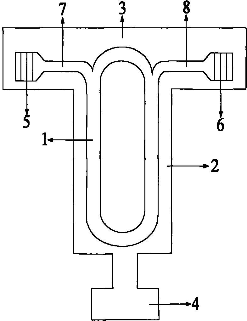
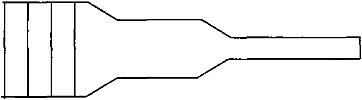
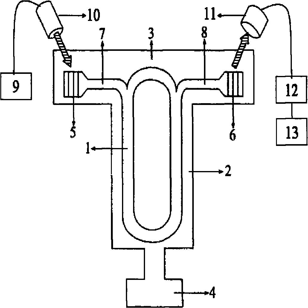
[0029] (1) Optical resonant cavity: Use photolithography technology to process the optical resonant cavity with integrated input and output on the top silicon of SOI and the silicon oxide material of the oxide layer. The silicon dioxide should also be etched to ensure the single mode of light in the silicon layer. transmission. The widths of the input optical waveguide end and the output optical waveguide end of the optical resonant cavity are 500nm-550nm, and the widths of the input optical waveguide and the output optical waveguide parallel to the two sides of the optical resonant cavity are 550nm-600nm, that is, the input optical waveguide end and the output optical waveguide end T...


PUM


Abstract

The invention relates to an optical cavity micro-accelerometer based on an integrated input/output terminal, which comprises an optical cavity, a cantilever beam, a substrate, a mass block, an input grating, an output grating, an input optical waveguide and an output optical waveguide. One end of the cantilever beam is connected with the substrate and the other end is connected with the mass block; the cantilever beam is formed by etching; the optical cavity is etched on the upper surface of the cantilever beam and is in the shape of a plane runway. The optical cavity micro-accelerometer is characterized in that the optical cavity comprises a three-layer structure from top to bottom; the optical cavity is integrated with the input/output terminal; and optical input and output ports are integrated with the optical cavity through a grating structure; and the input optical waveguide and the output optical waveguide are integrated with the optical resonant cavity. The optical cavity micro-accelerometer based on an integrated input/output terminal is made by modern MEMS (Micro-electromechanical System) process technology and is applicable to measurement of acceleration of vibration, impact and the like in a magnetic filed environment and a vacuum environment.

Description

Technical field [0001] The invention belongs to the technical field of micro-electromechanical systems, and mainly relates to a micro accelerometer, in particular to an optical resonant cavity micro accelerometer based on an integrated input and output terminal. Background technique [0002] In recent years, with the development and maturity of MEMS technology, micro-accelerometers with miniaturization, high sensitivity and strong anti-overload capability, such as piezoresistive micro-accelerometer, pressure-sensitive micro-accelerometer, etc. Vibration in the aerospace, electronic and mechanical manufacturing fields And the impact measurement has been well developed. However, this type of micro-accelerometer uses traditional electrical principles and is not suitable for complex electromagnetic fields and ultra-vacuum systems. At the same time, this type of micro-accelerometer forms a sensitive unit through an ion implantation process during the manufacturing process, which requ...

Claims


Application Information

Patent Timeline
Patent Type & Authority Applications(China)
IPC IPC(8): G01P15/03G02B6/34
Inventor 熊继军严英占闫树斌张文栋刘俊薛晨阳吉喆刘正赵敏李杰贾鹏飞
Owner ZHONGBEI UNIV
Why Eureka
Try Eureka