Smart filtering compensation module structure

A compensation module, intelligent filtering technology, applied in harmonic reduction devices, AC networks to reduce harmonics/ripples, boards/panels/desks of substations/switching devices, etc. The installation personnel are inconvenient to carry and install, and it is not conducive to the cost control of the manufacturer, so as to achieve the effect of novel structure, elimination of hidden safety hazards and low processing difficulty.

Inactive Publication Date: 2016-08-24
GUANGDONG GUANGDA ELECTRICAL
View PDF4 Cites 3 Cited by
  • Summary
  • Abstract
  • Description
  • Claims
  • Application Information

AI Technical Summary

Problems solved by technology

[0002] With the continuous use of the intelligent filter compensation module, the vulnerable parts in the module need to be replaced or overhauled; however, the traditional structure of the filter compensation module still has the following improvements: (1) The main control unit of the digital tube, the fan and the trigger board When replacing or overhauling devices, due to their structure, it takes a long time to disassemble and assemble, and the efficiency is not high; (2) The installation method of the knife fuse switch panel can only meet one type of knife fuse switch, which is not conducive to the production side. (3) Inside the existing module, the air duct can only satisfy the heat dissipation of the thyristor and the reactor, and the heat dissipation of other components still needs to be improved; (4) The weight of the 66.7kvar module reaches 75kg, the handling and installation of the installer is extremely inconvenient, and it is not conducive to packaging and transportation; (5) The reactor is directly connected to the thyristor terminal, because the reactor is hard-wired, it is easy to exist due to the force of the thyristor terminal The hidden danger of deformation affects the life of the thyristor and reduces the quality of the module; (6) The layout of the secondary line inside the module needs to be improved; (7) The installation of some components affects the installation of components, and the supply of components The delay will also affect the assembly of other parts, and the production efficiency is not high

Method used


Image

  • Smart filtering compensation module structure
  • Smart filtering compensation module structure
  • Smart filtering compensation module structure

Examples


Embodiment Construction

[0046] The present invention will be further described in detail with reference to the accompanying drawings and embodiments.

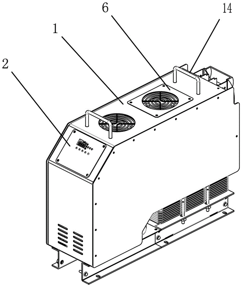
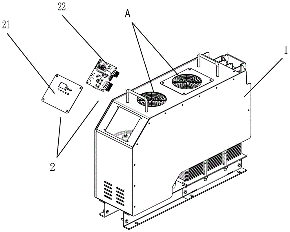
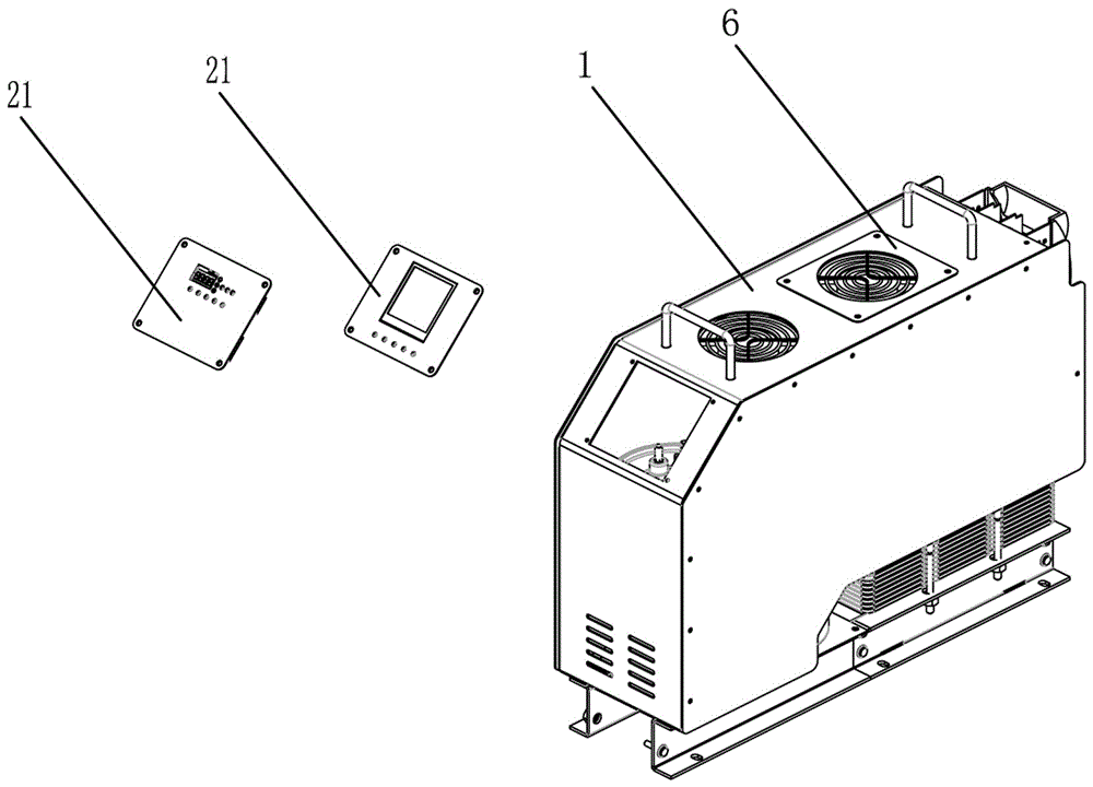
[0047] Such as Figure 1 to Figure 15 As shown in the figure, an intelligent filter compensation module structure includes a housing 1, and a capacitor C, a reactor 18, a thyristor 17, a trigger board 10 and a knife fuse switch 11 arranged in the housing 1, and it is characterized in that it also includes The main control unit 2, the fan assembly A and the knife fuse switch panel 9, the trigger plate 10 and the knife fuse switch pass 11 are fixed on the shell 1 through the knife fuse switch panel 9, the fan assembly A is installed on the surface of the shell 1, and the reactor 18 is connected with the fuse switch panel 9. The silicon controlled silicon 17 is electrically connected through the copper bar 16 , and the main control unit 2 is electrically connected with the knife fuse switch 11 , the silicon controlled silicon 17 , the trigger board 10 , ...


PUM


Abstract

The invention discloses a smart filtering compensation module structure. The structure comprises an enclosure, and a capacitor, an electric reactor, a silicon controlled rectifier and a fuse knife switch arranged in the enclosure. The structure is characterized in also comprising a main control unit, a fan assembly and a fuse knife switch panel. A triggering board and the fuse knife switch are fixed on the enclosure by the fuse knife switch panel. The fan assembly is mounted on the surface of the enclosure. The electric reactor and the silicon controlled rectifier are electrically connected by a copper bar. The main control unit is electrically connected with the fuse knife switch, the silicon controlled rectifier, the triggering board, the electric reactor and the capacitor. According to the smart filtering compensation module structure, the electric reactor and the silicon controlled rectifier are electrically connected by the copper bar, therefore, the stress of the wiring terminal of the silicon controlled rectifier is reduced, the conductive contact area is increased, and the potential safety hazards are eliminated. Moreover, the triggering board and the fuse knife switch are fixed on the enclosure by the fuse knife switch panel, therefore, replacement or overhaul can be carried out only by disassembling the fuse knife switch panel, the replacement and overhaul of the triggering board and the fuse knife switch are very convenient, and the integral structure is reasonable.

Description

technical field [0001] The invention relates to the technical field of intelligent filter compensation modules, in particular to an improved intelligent filter compensation module structure. Background technique [0002] With the continuous use of the intelligent filter compensation module, the vulnerable parts in the module need to be replaced or overhauled; however, the traditional structure of the filter compensation module still has the following improvements: (1) The main control unit of the digital tube, the fan and the trigger board When replacing or overhauling devices, due to their structure, it takes a long time to disassemble and assemble, and the efficiency is not high; (2) The installation method of the knife fuse switch panel can only meet one type of knife fuse switch, which is not conducive to the production side. (3) Inside the existing module, the air duct can only satisfy the heat dissipation of the thyristor and the reactor, and the heat dissipation of ot...

Claims


Application Information

Patent Timeline
Patent Type & Authority Applications(China)
IPC IPC(8): H02B1/04H02B1/56H02J3/01
CPCH02B1/04H02B1/56H02J3/01Y02E40/40
Inventor 吴文志田万春吴景营
Owner GUANGDONG GUANGDA ELECTRICAL
Why Eureka
Try Eureka