Supercharge Your Innovation With Domain-Expert AI Agents!

Simple-structured cylindrical cam horizontal pounding machine

A cylindrical cam technology with a simple structure is applied in the field of processing machinery to achieve the effects of improving production efficiency, simple transmission mode and high mechanical efficiency

Inactive Publication Date: 2016-08-31
成都市沃发特科技有限公司
View PDF0 Cites 0 Cited by
  • Summary
  • Abstract
  • Description
  • Claims
  • Application Information

AI Technical Summary

Benefits of technology

This new type of machinery uses an elliptical or circular disc that moves along rails for precise movement. It consists of two components - one powers its motor while another works together through gears. Its technical effect lies on simplifying construction, reducing wear caused by moving parts, improving work-performing performance, increasing productivity, lower costs associated with maintainability, lessening worker stress levels, etc., making it more efficient than previous methods.

Problems solved by technology

In this patented technical problem addressed in that patents by researchers at home and abroad for example, there have been attempts made manually to process certain foods like rice cake without causing damage due to excessive pressure applied on them when they were being worked outdoors over time. However, these techniques require large amounts of effort and expensive machinery which makes it challenges to maintain their quality and consistency throughout production.

Method used


Image

  • Simple-structured cylindrical cam horizontal pounding machine
  • Simple-structured cylindrical cam horizontal pounding machine

Examples


Embodiment

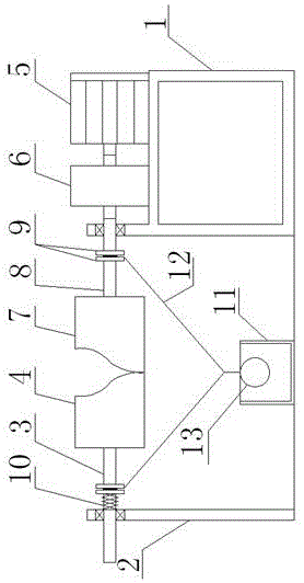
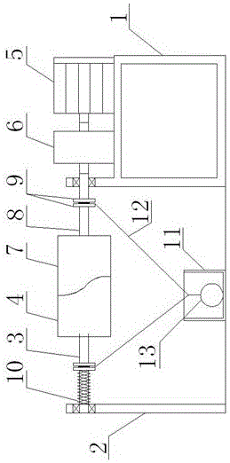
[0021] Such as figure 1 , figure 2 As shown, a cylindrical cam horizontal pounding machine with a simple structure includes a frame 1, a bracket 2, a driven shaft 3, a driving shaft 8, a motor 5 mounted on the frame 1 through bolts, and one end of the driven shaft 3 slides Connected to the bracket 2, it can do linear reciprocating motion on the bracket 2, the other end of the driven shaft 3 is connected with the passive cylindrical cam 4, the driving shaft 8 is connected to the frame 1 through the bearing rotation, between the driving shaft 8 and the motor 5 A reduction box 6 is connected, the other end of the driving shaft 8 is connected with a driving cylindrical cam 7, two baffle plates 9 are welded at intervals on the driving shaft 8 and the driven shaft 3, and the driving shaft 8 and the driven shaft 3 are bolted with cables 12 , wherein the wires 12 are respectively bolted between the intervals between the two baffles 9 provided on the driving shaft 8 and the intervals...


PUM


Abstract

The invention discloses a simple-structured cylindrical cam horizontal pounding machine. The simple-structured cylindrical cam horizontal pounding machine comprises a rack, a support, a driven shaft, a driving shaft and a motor arranged on the rack, wherein one end of the driven shaft is slidably connected onto the support; the other end of the driven shaft is connected with a driven cylindrical cam; the driving shaft is rotatably connected onto the rack; one end of the driving shaft is connected with the motor; the other end of the driving shaft is connected with a driving cylindrical cam; the driving shaft and the driven shaft are separately connected with a wire; the free end of each wire is connected with a pounding ball; and the rack and the support are arranged on the ground oppositely. Two baffle plates are arranged on the driving shaft at an interval; two baffle plates are arranged on the driven shaft at an interval; a spring is connected between the support and the baffle plates arranged on the driven shaft; the spring sleeves the driven shaft; and the lower part of the pounding ball is provided with a stone mortar which is matched with the pounding ball for use. The simple-structured cylindrical cam horizontal pounding machine has the advantages that the structure is simple; the mechanical efficiency is high; maintenance is convenient; no large impact is generated during transmission; and the yield is improved.

Description


Claims


Application Information

Patent Timeline
Owner 成都市沃发特科技有限公司
Features
  • R&D
  • Intellectual Property
  • Life Sciences
  • Materials
  • Tech Scout
  • Unparalleled Data Quality
  • Higher Quality Content
  • 60% Fewer Hallucinations
Learn More