U-shaped cutter of pulverizer

A pulverizer and cutter technology, applied in the field of pulverizer cutter structure, can solve the problems of unreasonable structure design, insufficient pulverized material precision, easy to stick to the bottom of the screen, etc., and achieve the effect of improving structural defects, avoiding the sticking of the bottom of the screen, and increasing the output.

Inactive Publication Date: 2016-08-31
YANTAI YUANHAO BIOTECH CO LTD
View PDF11 Cites 0 Cited by
  • Summary
  • Abstract
  • Description
  • Claims
  • Application Information

AI Technical Summary

Problems solved by technology

[0004] The present invention aims to solve the technical defects such as unreasonable structural design, easy to paste the bottom of the screen, and insufficient precision of crushed materials in the existing knives for pulverizers, and further provides a machine with reasonable structural design, high crushing effect, high crushing output, and is not easy to grind. A cutter for pasting the bottom of the sieve; further, the present invention also provides a pulverizer with the above-mentioned cutter at the same time

Method used


Image

  • U-shaped cutter of pulverizer
  • U-shaped cutter of pulverizer

Examples


Embodiment 1

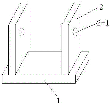
[0025] A U-shaped cutter of a pulverizer is movably installed on the rotating roller of the pulverizer. The overall shape of the U-shaped cutter is a U-shaped structure, and specifically includes: a tool holder 2 composed of two plate-shaped structures arranged in parallel longitudinally. The plate-like structure is respectively reserved with mounting shaft holes 2-1 with the axis on a straight line; a knife body 1 in a plate-like structure and installed transversely on the end of the tool holder 2 away from the mounting shaft hole 2-1, so The cutter body can be cut into a steel plate with the same width by using an old automobile spring steel plate without teeth or other tools. The cutter body 1 and the two plate-shaped structures of the cutter holder 2 are vertically fixedly connected. The structure of the two plates constituting the tool rest 2 uses two iron plates with a thickness of 4-5 mm. The tool rest cannot be made of steel plate, because the steel plate is brittle and...

Embodiment 2

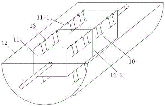
[0028] The pulverizer includes a rotating roller 11 installed on the frame, and a screen 12 located at the lower part of the rotating roller 11, and a U-shaped cutter 10 is installed on the rotating roller 11;

[0029] The tool 10 is composed of a tool holder 2 and a tool body 1; the tool holder 2 is composed of two plate-shaped structures arranged side by side in a longitudinal direction, and the two plate-shaped structures are respectively reserved for installation of shaft centers on a straight line. Shaft hole 2-1; the knife body 1 is a plate-shaped structure, which is installed transversely to the end of the knife holder 2 away from the mounting shaft hole 2-1, the knife body 1 and the two plates of the knife holder 2 Vertically fixed connection between the shaped structures. The two plate structures that make up the tool holder 2 are made of two 4-5mm thick iron plates; the plate structure that makes up the knife body 1 is made of steel; the difference between the tool hold...


PUM


Abstract

The invention relates to a U-shaped cutter of a pulverizer. The cutter is characterized in that the whole appearance of the cutter is of a U-shaped structure, and specifically comprises a cutter rest composed of two longitudinally-arranged plate-shaped structures; the plate-shaped structures are each provided with a mounting shaft hole in a reserving manner, and the axes of the mounting shaft holes are located on the same straight line; a cutter body is of a plate-shaped structure and is transversely mounted at the end, away from the mounting shaft holes, of the cutter rest; the cutter body is vertically and fixedly connected with the position between the two plate-shaped structures of the cutter rest; and the U-shaped cutter is reasonable, simple and rapid in novel structural design, and structural defects of an existing piece-shaped or hammer type cutter are overcome. Compared with a traditional cutter, the cutter has the beneficial effects that the material contact area is large, the cutter body has the cleaning effect on a material screening tool, and therefore for the materials of the same humidity, due to the U-shaped cutter, the screen bottom is not prone to being pasted.

Description

Technical field [0001] The invention relates to a cutter, especially a cutter used in a pulverizer. At the same time, the invention also provides a pulverizer with the cutter, belonging to the technical field of pulverizer cutter structure. Background technique [0002] The main crushing structure of the existing crusher includes a rotating roller on which a plurality of cutters are installed. When the rotating roller rotates, the cutter is driven to rotate at the same time, and the cutter rotates to pulverize materials at the same time. [0003] At present, the cutters commonly used in the above-mentioned grinders are hammer cutters or chip cutters. During the use of the grinder, the cutters are driven by the body to rotate and grind the materials. However, the disadvantages of this cutter structure are: When the moisture is greater than 10%, the bottom of the sieve may be pasted. The particle size requirements of the powder particles cannot be guaranteed, and at the same time t...

Claims


Application Information

Patent Timeline
IPC IPC(8): B02C18/18
CPCB02C18/18
Inventor 周洪昊周源
Owner YANTAI YUANHAO BIOTECH CO LTD
Why Eureka
Try Eureka