Three-point truss type girder bridge intelligent steel diaphragm

A type of diaphragm beam and truss technology, applied in the direction of bridges, bridge parts, bridge construction, etc., can solve the problem that the bridge cannot meet the strength requirements of the diaphragm beams, the welding quality of the diaphragm beams is poor, and the diaphragm beams are not coplanar, etc. problems, to achieve the effect of improving structural defects, avoiding construction difficulties, and reducing construction difficulties

Pending Publication Date: 2021-04-16
ZHEJIANG UNIV OF TECH
View PDF2 Cites 0 Cited by
  • Summary
  • Abstract
  • Description
  • Claims
  • Application Information

AI Technical Summary

Problems solved by technology

At the same time, in the process of assembling and connecting the concrete transverse beams, there will be problems such as non-coplanarity between the existing transverse beams, staggered platforms, poor welding quality of the transverse beam reinforcement or insufficient pouring, which makes the concrete transverse beams There are a series of problems in the structure of the beam itself, based on the defects in the construction process and the concrete transverse beam cannot meet the strength requirements of the current bridge for the transverse beam

Method used


Image

  • Three-point truss type girder bridge intelligent steel diaphragm
  • Three-point truss type girder bridge intelligent steel diaphragm
  • Three-point truss type girder bridge intelligent steel diaphragm

Examples


Embodiment Construction

[0029] The present invention will be further described in detail below with reference to the accompanying drawings and embodiments. It should be noted that the following embodiments are intended to facilitate the understanding of the present invention, but do not limit it in any way.

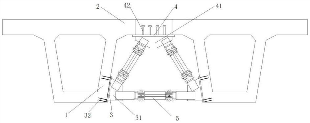
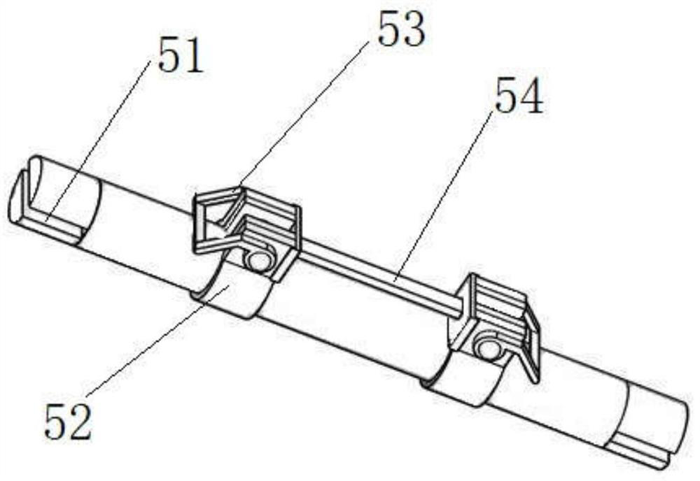
[0030] Such as Figure 1~3 As shown, a smart steel diaphragm of a three-point truss girder bridge is installed between the webs 1 of two adjacent small box girders or T-beams, including two pre-buried at the bottom of the adjacent webs 1 The lower steel plate 3, a top steel plate 4 pre-embedded in post-cast concrete between adjacent beam flanges 2, and three supporting steel pipes 5 respectively cooperating with the lower steel plate 3 and the top steel plate 4 to form a triangular support structure.

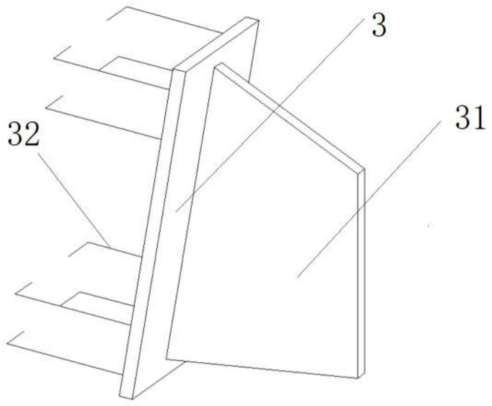
[0031] Specifically, such as figure 2 As shown, the lower steel plate 3 is vertically provided with a gusset plate 31 , and at the same time, the lower steel plate 3 is pre-embedded at the botto...


PUM


Abstract

The invention discloses a three-point truss type girder bridge intelligent steel diaphragm which is installed between webs of two adjacent small box girders or T-shaped girders, and comprises two lower steel plates which are pre-buried at the bottoms of adjacent web plates, a top steel plate which is pre-buried in post-poured concrete between adjacent beam flanges, and three supporting steel pipes which are respectively matched and fixed with the lower steel plates and the top steel plate to form a triangular supporting structure; joint plates are perpendicularly arranged on the lower steel plate and the top steel plate, and the supporting steel pipes are fixedly welded to the joint plates in a matched mode through welding seams formed in the two ends. By means of the concrete diaphragm beam, the structural defects caused by construction of an existing concrete diaphragm beam can be overcome, and the concrete diaphragm beam has the advantages of being low in self-weight, high in strength, easy and convenient to construct and the like.

Description

technical field [0001] The invention relates to the related technical field of bridge diaphragm beams in civil engineering, in particular to an intelligent steel diaphragm beam of a three-point truss type girder bridge. Background technique [0002] Diaphragm girder is a kind of transverse connection between the webs of small box girder or T girder in order to ensure the lateral stiffness of small box girder or T girder in girder bridge, while in prefabricated T girder bridge It plays a role in ensuring that the main girders are connected to each other as a whole. The greater its stiffness, the better the integrity of the bridge, and the better the main girders can work together under load. [0003] The Chinese patent document that publication number is CN204491428U discloses a kind of formwork that is used for the reinforcement of the diaphragm beam of bridge, and it comprises: U-shaped steel plate, steel bar and anchor bolt; U-shaped steel plate comprises base plate and tw...

Claims


Application Information

Patent Timeline
Patent Type & Authority Applications(China)
IPC IPC(8): E01D19/00
Inventor 彭卫兵陈大卫徐胜范大军李翠华
Owner ZHEJIANG UNIV OF TECH
Why Eureka
Try Eureka