Eureka AIR delivers breakthrough ideas for toughest innovation challenges, trusted by R&D personnel around the world.

A food waste slag liquid separator

A kitchen waste and separator technology, applied in liquid separation, filtration separation, separation methods, etc., can solve the problems of slow filtration, inability to quickly discharge kitchen waste solids, and non-compliance with environmental protection regulations, and achieve separation. Effect

Active Publication Date: 2017-11-24
重庆耐德生态科技有限公司
View PDF1 Cites 0 Cited by
  • Summary
  • Abstract
  • Description
  • Claims
  • Application Information

AI Technical Summary

Problems solved by technology

Although the filter tank of the device has achieved the effect of filtering and separating the oil in the food waste, the problems still exist in the device are: 1) the filter tank is only provided with a filter screen, so the food waste solid after separation still exists in the filter. 2) There is a filter screen fixed in the filter tank, after separation, the oil still exists in the filter tank, and the filter screen is in a static filtering state, which will not make the food waste solid Collision with warm water, so the filtration effect is not good, and the filtration speed is slow; 3) Since the solid food waste is a solid substance, its fluidity is far lower than that of fluid substances, so the single first solid slag conveying pipeline and the second The second solid slag conveying pipeline cannot quickly discharge solid food waste; 4) If only the first solid slag conveying pipeline or the second solid slag conveying pipeline is used to load the solid slag in the transport barrel, one transport barrel is full Afterwards, it is necessary to turn off the first solid slag conveying pipeline or the second solid slag conveying pipeline, and then change another empty transport barrel to connect to prevent the solid slag from falling on the ground to pollute the environment, which does not meet the environmental protection regulations; 5) no solution After filtering, how to remove the solid residue from the filter screen, clogging will occur during long-term use

Method used


Image

  • A food waste slag liquid separator
  • A food waste slag liquid separator
  • A food waste slag liquid separator

Examples


Embodiment Construction

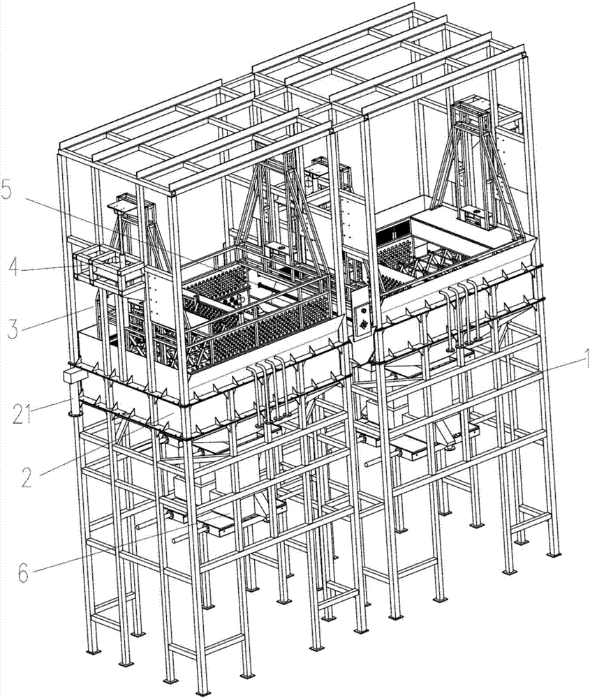
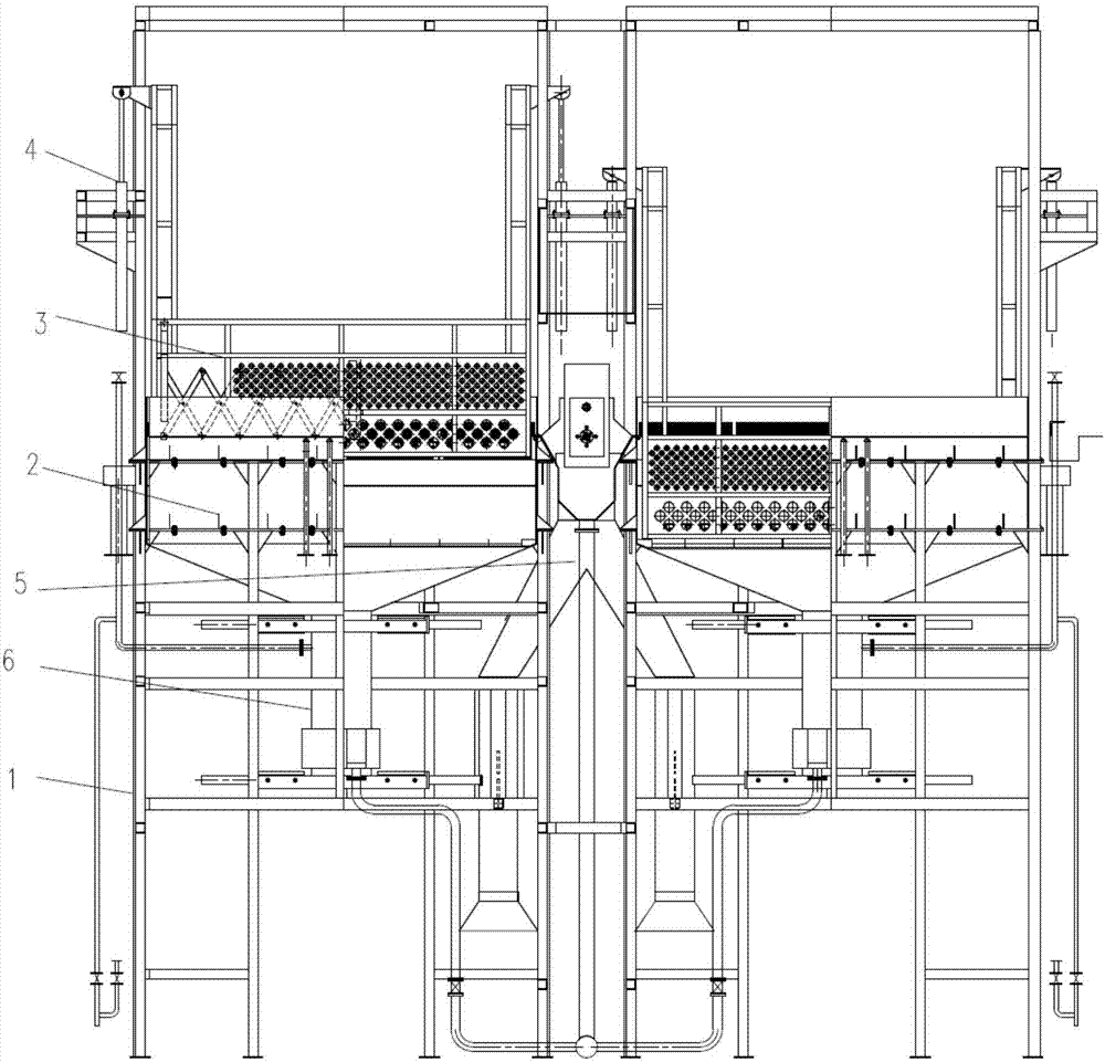
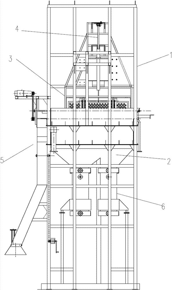
[0031] Such as Figure 1 to Figure 3 As shown, the present invention proposes a kitchen waste slag-liquid separator, comprising: a frame 1; a steel pool body 2 installed on the frame 1 to store warm water; a grate device is arranged above the steel pool body 2 3, to store food waste solids; on the frame 1, a lifting mechanism 4 is arranged, and the lifting mechanism 4 is connected with the trough device 3, so that the trough device 3 can be immersed in or out of warm water back and forth; on the frame 1 A draining and scraping tank 5 located next to the draining and scraping tank 3 is provided. When the lifting mechanism 4 lifts the draining and scraping tank 3 to a position flush with the draining and scraping tank 5, the draining and scraping tank 5 outputs meals to the draining and scraping tank 5. Kitchen waste solids, draining and scraping slag tank 5 is used to discharge the food waste solids into the transport barrel; a slag-liquid separator 6 is arranged at the bottom ...


PUM


Abstract

The invention provides a kitchen waste residue and liquid separator. The kitchen waste residue and liquid separator comprises a rack, a steel tank body arranged on the rack to store warm water, a grate groove device arranged above the steel tank body to store solid kitchen waste, a lifting mechanism arranged on the rack and connected with the grate groove device to enable the grate groove device to be immersed in or emerge out of the warm water circularly, a water leaching and residue scratching groove formed beside the grate groove device and in the rack, and a residue and liquid separator body arranged at the bottom of the steel tank body to separably discharge the warm water and solid residues in the mixed residue and liquid. The kitchen waste residue and liquid separator has the beneficial effects that the kitchen waste is rapidly placed into the warm water and is rapidly transferred from the warm water, the solid kitchen waste transferred out of the warm water is rapidly discharged and continuously conveyed into a transporting barrel, and solid residues of small particles in the residue and liquid mixture are separated from the warm water.

Description

technical field [0001] The invention relates to a slag-liquid separation device, in particular to a kitchen waste slag-liquid separator. Background technique [0002] In the food waste slag liquid separation process, it is necessary to separate the oil liquid from the food waste slag liquid. The specific operation of the oil-liquid separation process is: 1) Put the kitchen waste in warm water to make the oil float on the surface of the warm water; 2) When the oil level is too high, the oil will flow out automatically to realize the separation of oil and warm water 3) After all the oil floats on the surface of warm water, it is necessary to transfer most of the food waste solids from the warm water; 4) After separating most of the food waste solids, due to the small diameter of some solids, there will still be Part of the solid slag remains in the warm water to form a slag-liquid mixture, and it is necessary to separate the solid slag from the warm water. Therefore, the pro...

Claims


Application Information

Patent Timeline
Patent Type & Authority Patents(China)
IPC IPC(8): B09B3/00B09B5/00C02F1/40B01D36/04
CPCB01D36/04B09B3/00B09B5/00C02F1/40
Inventor 周生阳宋淼冷广州王海云徐特杨林波瞿忠卫张智友向小木
Owner 重庆耐德生态科技有限公司
Why Eureka
Eureka Blog
Learn More