Electric spin-flaring equipment

An electric and equipment technology, applied in the field of electric spinning and flaring equipment, can solve the problems of cumbersome use, affecting the efficiency of processing, inability to move flexibly, etc., and achieve the effects of high production efficiency, good sealing effect, and simple and flexible structure.

Inactive Publication Date: 2016-08-31
苏州巴茨流体动力技术有限公司
View PDF5 Cites 2 Cited by
  • Summary
  • Abstract
  • Description
  • Claims
  • Application Information

AI Technical Summary

Problems solved by technology

[0002] Conventional flaring machines are mostly manual flaring machines, which are cumbersome to use and require manual pressing of the manual pump, which greatly affects the processing efficiency and cannot be moved flexibly.

Method used


Image

  • Electric spin-flaring equipment
  • Electric spin-flaring equipment
  • Electric spin-flaring equipment

Examples


Embodiment Construction

[0020] The present invention will be described in detail below with reference to the accompanying drawings and in combination with embodiments.

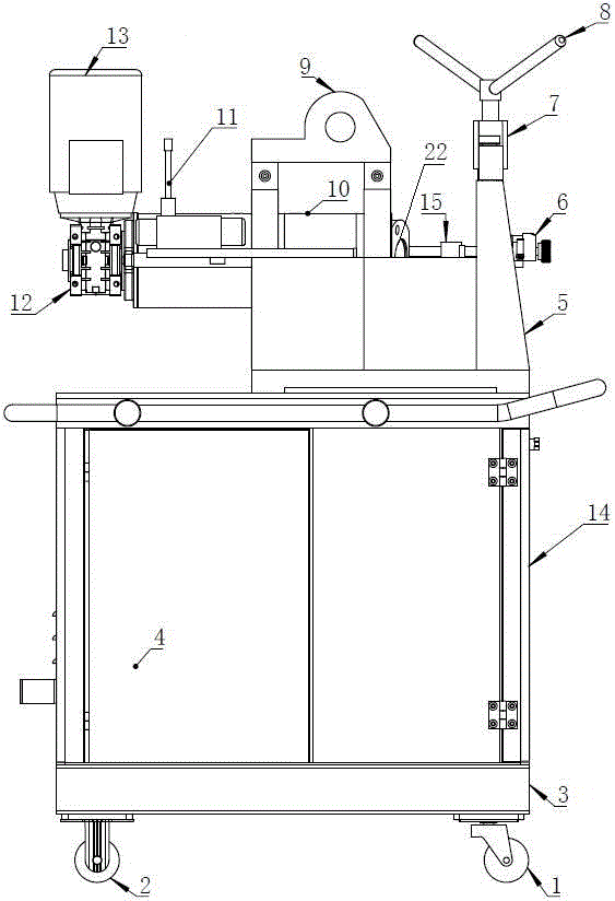
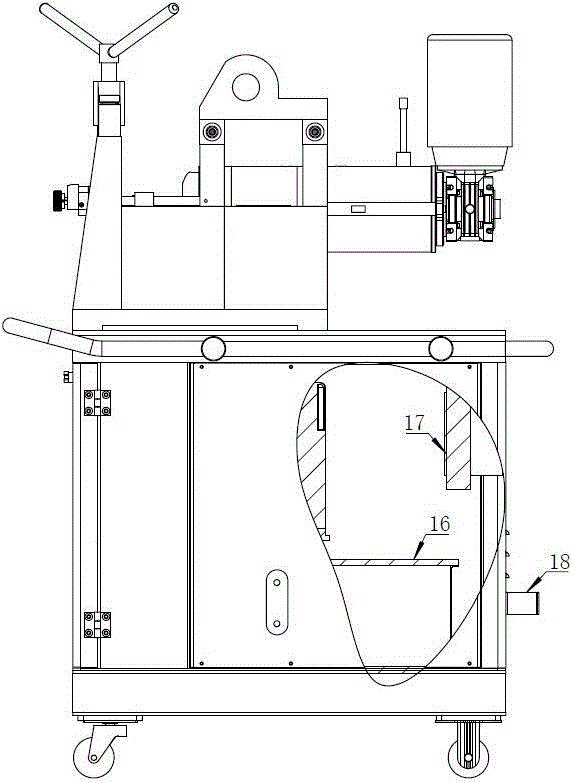
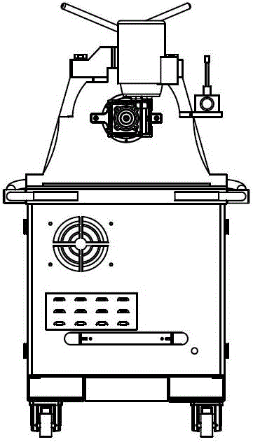
[0021] refer to Figure 1 to Figure 6 As shown, a kind of electric spinning flaring equipment comprises box body 3, and described box body 3 upper end is provided with casting base 5, is provided with oil cylinder 10 along its length direction in the middle of described casting base 5, and the oil cylinder 10 The rod end of the cylinder is connected to a vertical motor 13 through a reducer 12. One side of the casting base 5 is provided with a multi-way valve 11, and the other side of the casting base 5 is provided with a position indicator 6 and a limit plate 15. 5. A lifting lug 9 is fixedly connected to the middle position in the length direction, and a protruding part is provided at the other end of the casting base 5 relative to the motor 13, and a casting cover 7 is provided on the top of the protruding part, and the casting cov...


PUM


Abstract

The invention relates to electric spin-flaring equipment. The electric spin-flaring equipment comprises a box. A casting base is arranged at the upper end of the box. An oil cylinder is arranged in the middle of the casting base in the length direction. A cylinder rod end of the oil cylinder is connected with a vertical motor through a speed reducer. A multi-way valve is arranged on one side of the casting base. A displayer and a limiting plate are arranged on the other side of the casting base. A lifting lug is fixedly connected to the middle position, in the length direction, of the casting base. A protruding part is arranged at the other end, opposite to the motor, of the casting base. A casting cover is arranged at the top of the protruding part. A turning piece is connected to the casting cover in a screwed mode through threads. The lower end of the turning piece is fixedly connected with a pressing block. A separation plate clamp is arranged at the lower end of the pressing block. A pipe cavity is formed in the separation plate clamp. By the adoption of the equipment, the problems that nonuniformity is likely to be caused during steel pipe flaring and cracks are caused during flaring of steel pipes made of different materials can be solved; and in addition, the structure is flexible, an ordinary welding way can be replaced, the sealing effect is good, and the production efficiency is high.

Description

technical field [0001] The invention belongs to the field of spinning and expanding mechanical equipment, and in particular relates to an electric spinning and expanding equipment. Background technique [0002] Conventional flaring machines are mostly manual flaring, which is cumbersome to use and requires manual pressing of the manual pump, which greatly affects the processing efficiency and cannot be moved flexibly. Therefore, due to the existence of the above-mentioned problems, it is necessary to improve the above-mentioned equipment to improve its production efficiency, convenience and quickness. Contents of the invention [0003] The object of the present invention is to overcome the problems existing in the prior art and provide an electric spinning and flaring device. [0004] In order to achieve the above-mentioned technical purpose and achieve the above-mentioned technical effect, the present invention is realized through the following technical solutions: [0...

Claims


Application Information

Patent Timeline
Patent Type & Authority Applications(China)
IPC IPC(8): B21D41/02B21D22/14
CPCB21D41/02B21D22/14
Inventor 刘玮玮王殿臣
Owner 苏州巴茨流体动力技术有限公司
Why Eureka
Try Eureka