Clamp for display vibration test and installation method for same

A vibration test and installation method technology, applied in the direction of workpiece clamping device, manufacturing tools, etc., can solve the problems of long test period, low versatility, poor flexibility, etc., and achieve fixture processing cost saving, strong flexibility, and high work efficiency Effect

Active Publication Date: 2016-08-31
ZHUZHOU CSR TIMES ELECTRIC CO LTD
View PDF5 Cites 14 Cited by
  • Summary
  • Abstract
  • Description
  • Claims
  • Application Information

AI Technical Summary

Problems solved by technology

[0004] In view of this, the object of the present invention is to provide a display vibration test fixture and its installation method, which can solve the technical problems of poor flexibility, low versatility, high cost, and long test cycle of the existing overall frame-type vibration fixture

Method used


Image

  • Clamp for display vibration test and installation method for same
  • Clamp for display vibration test and installation method for same
  • Clamp for display vibration test and installation method for same

Examples


Embodiment Construction

[0051] In order to make the purpose, technical solutions and advantages of the embodiments of the present invention more clear, the technical solutions in the embodiments of the present invention will be clearly and completely described below in conjunction with the drawings in the embodiments of the present invention. Apparently, the described embodiments are only some of the embodiments of the present invention, not all of them. Based on the embodiments of the present invention, all other embodiments obtained by persons of ordinary skill in the art without creative efforts fall within the protection scope of the present invention.

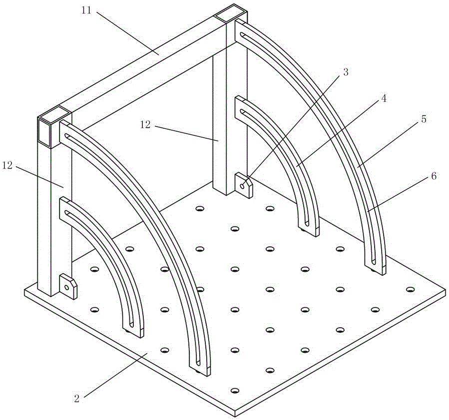
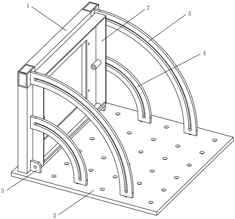
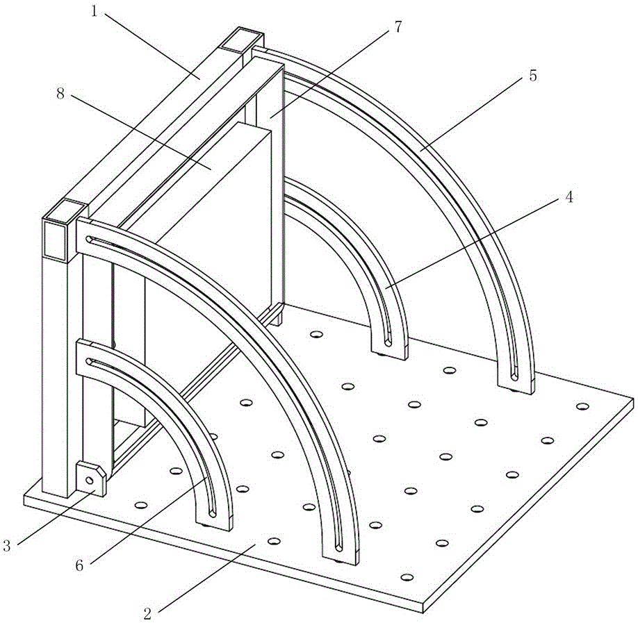
[0052] as attached figure 1 to attach Figure 13 As shown, specific embodiments of the display vibration test fixture and its installation method of the present invention are given, and the present invention will be further described below in conjunction with the accompanying drawings and specific embodiments.

[0053] as attached figure 1 to ...


PUM


Abstract

The invention discloses a clamp for a display vibration test and an installation method for the same. The clamp comprises a baseplate which is firmly installed on the surface of a vibration test table, a supporting frame disposed on one side of the base plate, a slide rail assembly disposed on left and right sides of the supporting frame and connected between the supporting frame and the baseplate, as well as an installation panel, wherein the slide rail assembly comprises a fixation base, a first slide rail and a second slide rail, and both the first slide rail and the second slide rails are equipped with arc slideways; and the bottom of the installation panel is in a hinged connection with the joint between the supporting frame and the baseplate, and the installation panel can move along the slideways and is used for firm installation of a display. Bolts penetrate the fixation base and the slideways and are screwed into studs on inner sides of left and right edges of the installation panel; the installation panel is rotated along the slideways with a rotary fixation hole of the fixation base as the axis till the angle of the installation panel is equal to a display truck loading angle; the baseplate is installed on the surface of the vibration test table by fastening bolts; and finally a test can be implemented. The clamp and the method disclosed by the invention can solve the technical problems that an existing vibration clamp with an overall frame structure has low flexibility, low universality, the high cost and long testing duration.

Description

technical field [0001] The invention relates to the technical field of electrical equipment testing, in particular to an angle-adjustable vibration test fixture applied to a liquid crystal display and an installation method thereof. Background technique [0002] Vibration test is a type of test that simulates the impact of various vibration environments encountered by products in the transportation, installation and use environments, and is used to determine whether the product can withstand various environmental vibrations. It is mainly used to evaluate components and parts. And the resistance of the whole machine in the expected transportation and use environment. Among them, as an important part of the vibration test system, the function of the vibration fixture is to transfer the energy of the vibration table to the tested sample. The design principle is to make the fixture as small as possible and as rigid as possible under the premise of satisfying the installation of ...

Claims


Application Information

Patent Timeline
Patent Type & Authority Applications(China)
IPC IPC(8): B25B11/00
CPCB25B11/00
Inventor 刘国涛吴永生余锋陈彪罗亚平姜华黄成周溢韬
Owner ZHUZHOU CSR TIMES ELECTRIC CO LTD
Why Eureka
Try Eureka