Forced continuous sprag clutch

A clutch and continuous technology, applied in the direction of clutches, one-way clutches, magnetic drive clutches, etc., can solve the problems of easy breakage of wedges, rising manufacturing costs, and wear of spring surfaces, so as to improve equipment safety and reliability. Effects of avoiding clutch failure and improving wedge strength

Inactive Publication Date: 2016-08-31
CENT SOUTH UNIV
View PDF8 Cites 5 Cited by
  • Summary
  • Abstract
  • Description
  • Claims
  • Application Information

AI Technical Summary

Problems solved by technology

[0003] However, there are deficiencies in the existing forced continuous sprag clutches: the springs that keep the sprags in contact with the inner and outer rings will produce fatigue fractures under cyclic stress, which will cause the clutch to fail; The stress distribution along the length is M-shaped, and the surface contact stress corresponding to the root of the groove is the largest (such as image 3 ), the wedge is prone to fracture here under a large impact load
Due to the long-term contact between the spring and the wedge groove and the vibration of the spring wire relative to the wedge, the spring is prone to surface wear and fatigue fracture; in addition, due to the influence of the spring groove, the stress distribution of the wedge along the axial direction is M-shaped, The contact stress is the largest at the position corresponding to the bottom of the groove, and the wedge is prone to fracture at this position
The failure of the spring and wedge will directly affect the service life of the forced continuous clutch and the safety of the equipment, and the groove of the wedge will also increase the manufacturing cost

Method used


Image

  • Forced continuous sprag clutch
  • Forced continuous sprag clutch
  • Forced continuous sprag clutch

Examples


Embodiment Construction

[0018] The present invention will be further described below in conjunction with the accompanying drawings and embodiments.

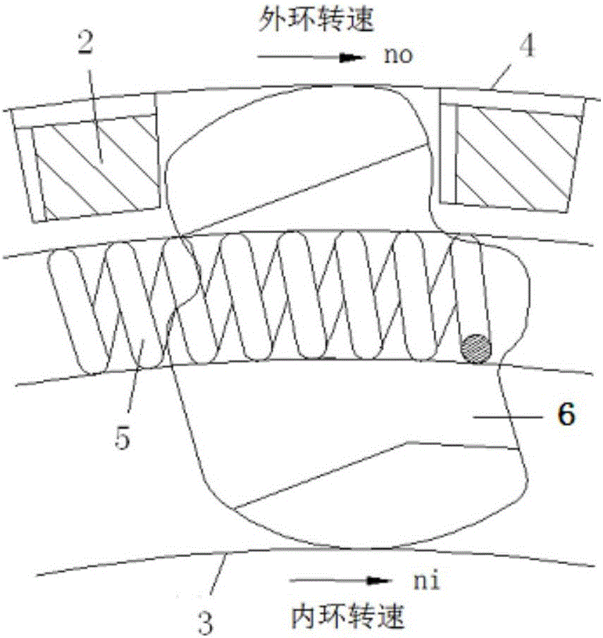
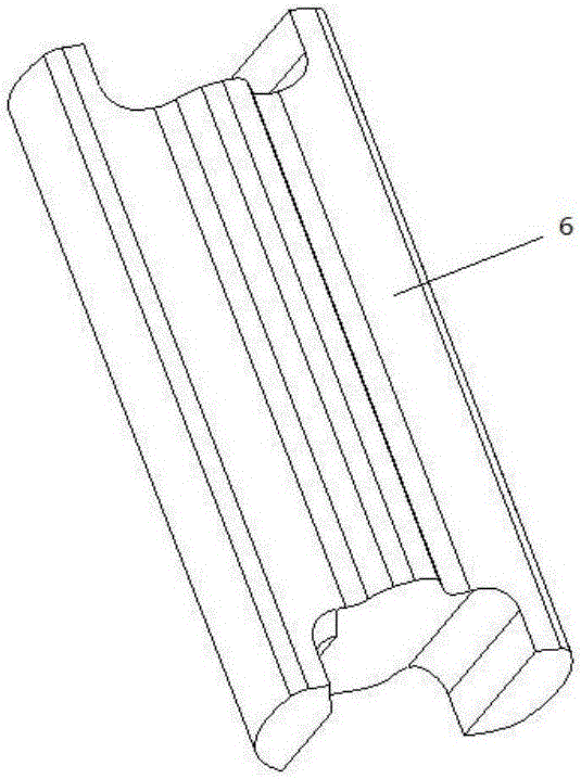
[0019] see Figure 4 and Figure 5 , the forced continuous sprag clutch provided by the present invention is composed of a cage 2, an inner ring 3, an outer ring 4 and a weak magnetic wedge 1. The end face of the weak magnetic wedge 1 is a planar structure; the inner ring 3 and the outer ring 4 It is a ferromagnetic material, and the cage 2 is a non-ferromagnetic material.

[0020] Specifically, the magnetic attraction force F between the weak magnetic wedge 1 and the inner ring 3 and outer ring 4 is controlled within 0.62-0.93N.

[0021] The magnetization B of the weak magnetic wedge 1 is calculated by the formula: F=(B / 4965)2*S, where F is the magnetic force kgf; B is the magnetic flux density G; S is the area perpendicular to the magnetic flux density cm 2 .

[0022] Specifically, the material of the weak magnetic wedge 1 is GCr15; the material o...


PUM


Abstract

The invention discloses a forced continuous sprag clutch. The forced continuous sprag clutch comprises a wedge block (1), a holder (2), an inner ring (3) and an outer ring, wherein the wedge block is a weakly-magnetic wedge block (1) of which the end surface is of a plane structure; the inner ring (3) and the outer ring (4) are manufactured from ferromagnetic materials; the holder (2) is manufactured from non-ferromagnetic material. According to the forced continuous sprag clutch, the weakly-magnetic wedge block is adopted and can be in contact with the inner ring and the outer ring all the time can be achieved, thus a spring of an original forced continuous sprag clutch and an original groove for mounting the spring can be removed, and as a result, the failure of the clutch caused by the failure of the spring can be avoided; meanwhile, the strength of the wedge block can be improved, so that the bearing capacity of the clutch can be improved, the service life of the clutch can be prolonged, and the difficulty in processing of the wedge block can be reduced; the forced continuous sprag clutch is outstanding in comprehensive effect.

Description

technical field [0001] The invention relates to a sprag clutch, in particular to a forced continuous sprag clutch used in equipment such as a high-power high-speed helicopter reducer. Background technique [0002] The forced continuous sprag clutch is a kind of overrunning clutch that can be used in the transmission system of helicopters and other equipment. It has the characteristics of large load capacity, reliable clutch and simple structure. The existing forced continuous sprag clutch is composed of a group of wedges 6, cage 2 and spring 5, etc., and the clutch is installed in the outer ring 4 and the inner ring 3, such as figure 1 and figure 2 . [0003] However, there are deficiencies in the existing forced continuous sprag clutches: the springs that keep the sprags in contact with the inner and outer rings will produce fatigue fractures under cyclic stress, which will cause the clutch to fail; The stress distribution along the length is M-shaped, and the surface c...

Claims


Application Information

Patent Timeline
Patent Type & Authority Applications(China)
IPC IPC(8): F16D27/01F16D41/06
CPCF16D27/01F16D41/06F16D2041/0603F16D2500/10493
Inventor 严宏志张美玉刘志辉姚毅曹煜明
Owner CENT SOUTH UNIV
Why Eureka
Try Eureka