

LED light emitting device and LED filament lamp
An LED filament lamp and LED filament technology are applied in lighting devices, lighting device parts, semiconductor devices of light-emitting elements, etc., which can solve the problems of many processes, small heat dissipation area, small filament surface area, etc. Large heat dissipation area and good heat dissipation performance
- Summary
- Abstract
- Description
- Claims
- Application Information
AI Technical Summary
Problems solved by technology
Method used
Image

Examples
Embodiment 1
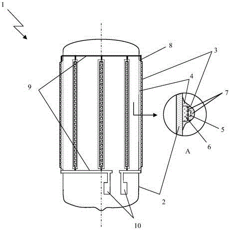
[0033] figure 1 A schematic structural diagram of the LED lighting device of Embodiment 1 of the present invention is given schematically, as shown in figure 1 As shown, the LED lighting device 1 includes:
[0034] A closed container 2, the air pressure in the closed container is less than 1 atmospheric pressure, and there is no heat transfer medium with phase change;
[0035] At least one LED filament 3, the LED filament 3 is any one of various existing LED filaments, including:
[0036] At least two LED chips 5, the at least two LED chips are fixed on the side of the substrate, and there is a luminescent powder layer 7 around the LED chips;
[0037] Substrate 6, such as a transparent glass substrate, a ceramic substrate, an opaque metal substrate, etc., the non-LED chip mounting surface of the substrate along the opposite sides of the LED chip arrangement direction are fixed on the closed by glue 4 On the outer wall of the container; the side of the substrate opposite to ...
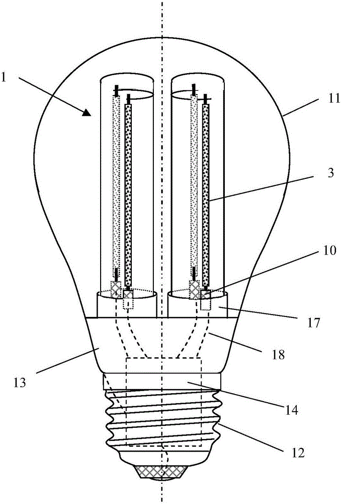
Embodiment 2
[0042] The LED light-emitting device of Embodiment 2 of the present invention is different from Embodiment 1 in that:
[0043] No substrate is used in the LED filament, and the contact surface of the LED filament opposite to the outer wall of the closed container is in direct or indirect contact with the outer wall (there is a luminescent powder layer between the contact surface and the outer wall), and the LED filament passes through the glue fixed on the outer wall.
Embodiment 3
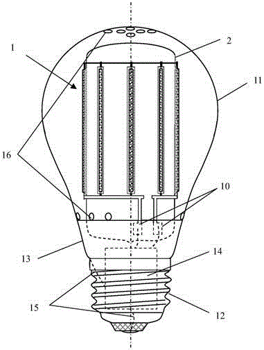
[0045] An application example of the LED lighting device according to Embodiment 1 of the present invention in an LED filament lamp.
[0046] Such as figure 2 As shown, the LED filament lamp includes:
[0047] Bulb shell 11, electrical connector 12, connector 13 and LED driver 14; These are the prior art in this field; Described bulb shell 11 is made of glass or plastics, and the upper and lower two ends of described bulb shell 11 respectively have At least one through hole 16, such as a series of through holes at the upper and lower ends, that is, the center of the series of through holes at the upper and lower ends is coplanar to the axis of the bulb, the center of the part of the through holes at the upper end and the part of the through holes at the lower end The perpendicular lines to the axis of the bulb are straight lines in different planes, so that the outside air enters from the lower through hole, quickly convects in the bulb, and is discharged from the upper thro...
PUM
 Abstract
Description
Claims
Application Information