Residential side-wall type pore plate air supply inlets

A technology of air supply port and orifice plate, which is applied in the field of residential side wall type orifice plate air supply port, which can solve the problems that indoor pollutants cannot be effectively eliminated, cannot be reached, and are unfavorable to human health.

Inactive Publication Date: 2016-08-31
北京市卡姆福科技有限公司
View PDF8 Cites 9 Cited by
  • Summary
  • Abstract
  • Description
  • Claims
  • Application Information

AI Technical Summary

Problems solved by technology

However, indoor pollutants cannot be effectively eliminated. If things go on like this, it will cause symptoms such as fatigue, headache, and drowsiness of indoor personnel, which is not conducive to health
According to the actual measurement, the indoor air CO2 concentration of the top-supply and top-return air supply method with the doors and windows closed for a long time is about 1100-1300ppm, which cannot meet the requirement of the CO2 concentration not exceeding 1000ppm stipulated in the "Indoor Air Quality Standard" GBT18883-2002

Method used


Image

  • Residential side-wall type pore plate air supply inlets
  • Residential side-wall type pore plate air supply inlets
  • Residential side-wall type pore plate air supply inlets

Examples


Embodiment Construction

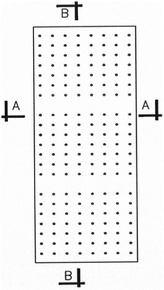
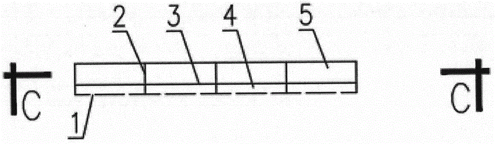
[0016] like Figure 1-6 As shown, the marks 1-18 in the figure are 1, orifice tuyere 2, longitudinal partition 3, horizontal partition 4, vertical side air duct front cavity 5, vertical side air duct rear cavity 6, The open flange is connected to the air duct.

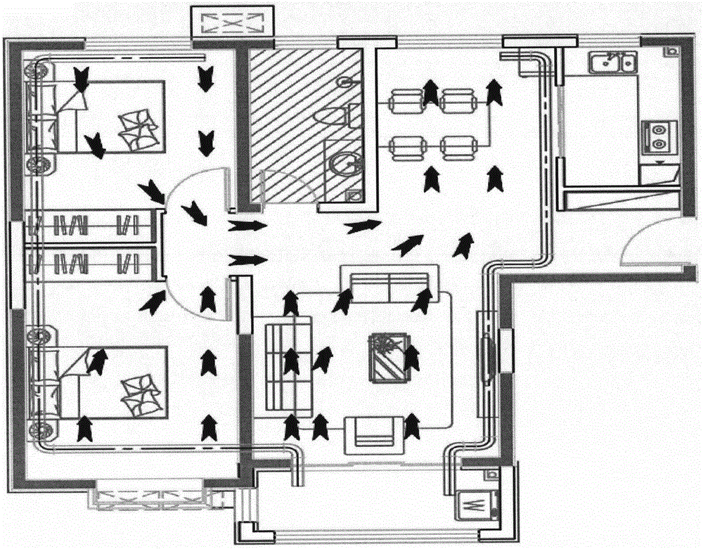
[0017] Vertical and horizontal partitions are installed in the vertical air duct of the side wall to stabilize the air flow and equalize the pressure. The front side cavity of the vertical side air duct is evenly provided with orifice air outlets on the side panel facing the room; the vertical side wind Channels, partitions, orifice plates, etc. are formed by injection molding or one-time stamping.

[0018] The vertical air duct has a thickness of 40-60mm, the distance between the longitudinal partitions is 40mm-200mm; the distance between the horizontal partition and the orifice plate is 10mm-30mm; the front cavity of the vertical side air duct faces the indoor side with holes Plate air supply; the top or lower open...


PUM


Abstract

Provided are residential side-wall type pore plate air supply inlets. A side wall vertical air duct is arranged, a longitudinal partition plate is additionally arranged in the air duct, so that the stability of air flow hydraulic characteristics is ensured. The speed of air supplied into the side wall vertical air duct is reduced to about 2 m/s, and the side wall vertical air duct is made to play a role of approximately a plenum chamber. The pore plate air supply inlets are evenly formed in a panel on the side, facing the indoor, of the side wall vertical air duct. In order to further evenly distribute air flow, transverse partition plates are arranged in the position with a certain distance to the panel provided with the air supply inlets in a sectional mode, and the velocity filed and the temperature field of discharged air flow can be evenly distributed. The shortcoming that a conventional diluted type air flow distribution cannot effectively remove indoor pollutants is overcome; treated fresh air flow can be pushed to a doorway evenly along a fracture surface of a room under the action of differential pressure between the air supply inlets and air discharge outlets, and is discharged through air discharge outlets formed in a corridor or a bathroom, and a similar-to-displacement type stable and even airflow field is formed; indoor pollutants of all varieties can be effectively eliminated; and a user can feel more comfortable in the fresh and clean airflow field, and the whole system is environmentally friendlier and saves energy.

Description

technical field [0001] The invention of the side wall type orifice air supply port of this house involves the combination of the vertical air supply channel and the terminal air supply device, which can effectively ensure the uniformity of the air supply velocity field and temperature field at the end of the cooling and heating air conditioner and the normal temperature air supply system. Basically, it guarantees the comfortable use of the residential replacement ventilation airflow organization adapted to it. Background technique [0002] With the promulgation and implementation of my country's "Indoor Air Quality Standard" GBT18883-2002, and the "Technical Regulations for Residential Fresh Air System" was included in the 2015 compilation plan, the residential fresh air system has attracted more and more attention. At present, the commonly used residential fresh air supply method in the market is a "diluted" airflow organization such as top supply and top return, which keep...

Claims


Application Information

Patent Timeline
Patent Type & Authority Applications(China)
IPC IPC(8): F24F7/04F24F13/068
CPCF24F7/04F24F13/068F24F2007/0025
Inventor 苏红王秀荣
Owner 北京市卡姆福科技有限公司
Why Eureka
Try Eureka