Multi-stage heat storage device and copious cooling liquefied air energy storage system using multi-stage heat storage technology

A heat storage device and energy storage system technology, applied in refrigeration and liquefaction, liquefaction, refrigerators, etc., can solve the problems of low thermal energy storage rate and uneven thermal energy quality, and achieve high-quality results

Inactive Publication Date: 2016-08-31
GLOBAL ENERGY INTERCONNECTION RES INST CO LTD +1
View PDF6 Cites 7 Cited by
  • Summary
  • Abstract
  • Description
  • Claims
  • Application Information

AI Technical Summary

Problems solved by technology

[0004] Therefore, the technical problem to be solved by the present invention is to overcome the technical defects of low thermal energy storage rate in the heat storage device in the prior art, and when outputting thermal energy, the output temperature is different and the quality of the output thermal energy is not uniform.

Method used


Image

  • Multi-stage heat storage device and copious cooling liquefied air energy storage system using multi-stage heat storage technology
  • Multi-stage heat storage device and copious cooling liquefied air energy storage system using multi-stage heat storage technology
  • Multi-stage heat storage device and copious cooling liquefied air energy storage system using multi-stage heat storage technology

Examples


Embodiment 1

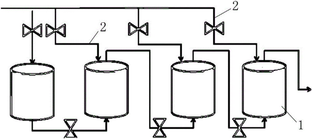
[0033] refer to figure 1 , this embodiment provides a multi-stage heat storage device, including a number of heat storage devices 1, the number of heat storage devices 1 is not less than 2, and any heat storage device 1 is connected to the thermal energy output end, so as to receive the heat energy output from the thermal energy output end. The thermal energy is stored in parallel, and the adjacent storage devices 1 are connected in series through the heat transfer channel 2, so that during the heat storage process, the heat energy escaped from the heat storage process of the previous stage heat storage 1 can enter through the heat transfer channel 2 to the heat storage device 1 of the subsequent stage, so as to preheat the heat storage device 1 of the subsequent stage. Moreover, the heat storage device 1 of the previous stage and the heat storage device 1 of the subsequent stage are used to store heat energy in different temperature ranges, so that when the heat energy is out...

Embodiment 2

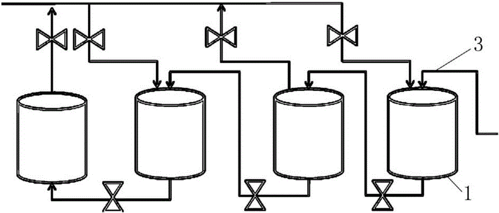
[0045] The difference between this embodiment and Embodiment 1 is that in this embodiment, only one of several heat storage devices 1 is used to connect to the output end of heat energy, and during the heat storage process, the heat energy is sequentially stored in the heat storage devices 1 at various levels. In, the energy release process is the same as in Example 1.

[0046] Compared with Example 1, this heat storage method still contains more heat energy in the escaped exhaust gas, but the exhaust gas discharged from the heat storage device 1 of the previous stage can still be pre-heated for the heat storage device 1 of the subsequent stage. Therefore, compared with the heat storage device in the prior art, the heat storage rate can still be improved to a certain extent, and the waste of heat energy can be reduced.

Embodiment 3

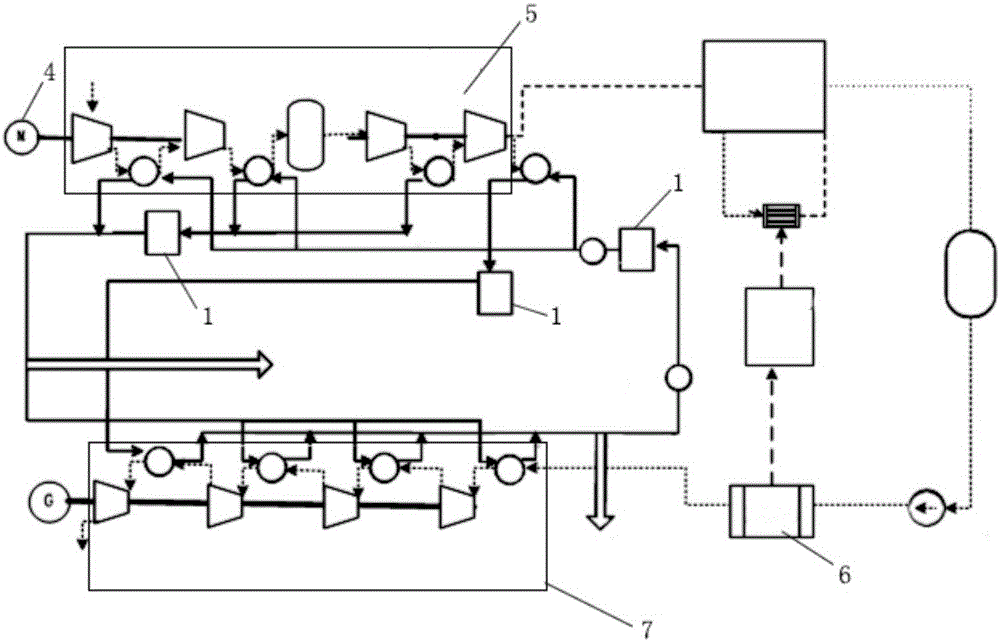
[0048] The following combination image 3 Describe in detail the multi-stage heat storage device of the cryogenic liquefied air energy storage system using the multi-stage heat storage technology provided in this embodiment. The multi-stage heat storage device of the cryogenic liquefied air energy storage system using the multi-stage heat storage technology includes: an energy input device 4, Used to input energy into the energy storage system;

[0049] The air compression device 5 is driven by the energy input device 4 to compress gaseous air into liquid air;

[0050] Gasification device 6, gasifying the liquid air;

[0051] And, the multi-stage heat storage device described in Embodiment 1 or 2 stores heat energy generated during the liquefaction of gaseous air in the air compression device 5 .

[0052] The above-mentioned embodiment is the core technical solution of this embodiment. The multi-stage heat storage device described in Embodiment 1 or 2 is used in combination ...


PUM


Abstract

The invention provides a multi-stage heat storage device and a copious cooling liquefied air energy storage system using the multi-stage heat storage technology. The heat storage device comprises at least two heat storage devices; every two adjacent heat storage devices are connected in series by means of a heat transfer channel; at least one heat storage device is connected with the heat energy output end; in the heat storage process, heat energy overflowing in the heat storage process of the previous stage of heat storage device enters the later stage of heat storage device by means of the heat transfer channel to preheat the later stage of heat storage device; and tail gas released by the previous stage of heat storage device still contains certain heat energy, after the later stage of heat storage device is preheated, heat energy in the tail gas can be exchanged into heat storage media in the heat storage devices to a large extent, and therefore the heat energy storage rate can be increased to a large extent, and heat energy waste is avoided.

Description

technical field [0001] The invention relates to the technical field of thermal energy storage and transportation, in particular to a multi-stage heat storage device and a multi-stage heat storage device for a cryogenic liquefied air energy storage system using the multi-stage heat storage technology. Background technique [0002] Deep heat liquefied air energy storage technology refers to the use of electric energy for compressed air during the low load period of the grid, and the high-pressure sealing of the air in abandoned mines, subsidence subsea gas storage tanks, caves, expired oil and gas wells or newly built gas storage wells. The energy storage method releases compressed air during the peak period to drive the steam turbine to generate electricity. The liquid air energy storage system has the advantages of large energy storage capacity, long energy storage period, small footprint and does not depend on geographical conditions. During energy storage, the electric ene...

Claims


Application Information

Patent Timeline
Patent Type & Authority Applications(China)
IPC IPC(8): F25J5/00F25B39/02F25B1/10F25B43/00
CPCF25J5/00F25B1/10F25B39/02F25B43/00F25B43/006
Inventor 金翼宋鹏翔胡晓王乐宋洁赵波徐桂芝邓占锋杨岑玉汤广福李志远梁立晓
Owner GLOBAL ENERGY INTERCONNECTION RES INST CO LTD
Why Eureka
Try Eureka