Calibration method of inertial unit optical aiming prism installation error

A technology for optical aiming and installation errors, applied in the direction of measuring devices, instruments, theodolite, etc., can solve the problems of incomplete parameter calibration, high requirements for testing equipment, limited application range, etc., to avoid expensive and deduct poor vertical plate indicators , the effect of reducing requirements

Active Publication Date: 2016-08-31
THE GENERAL DESIGNING INST OF HUBEI SPACE TECH ACAD
View PDF4 Cites 40 Cited by
  • Summary
  • Abstract
  • Description
  • Claims
  • Application Information

AI Technical Summary

Problems solved by technology

[0004] The present invention mainly aims at the deficiencies in the current inertial group optical aiming prism installation error calibration, such as high requirements for testing equipment, high cost, poor versatility, or incomplete parameter calibration, and limited use range, and proposes a method that can reduce the cost of testing equipment. Requirements and calibration costs, while ensuring the same calibration accuracy, comprehensive parameter calibration, and a highly versatile calibration method

Method used


Image

  • Calibration method of inertial unit optical aiming prism installation error
  • Calibration method of inertial unit optical aiming prism installation error
  • Calibration method of inertial unit optical aiming prism installation error

Examples


Embodiment Construction

[0052] The present invention will be further described below in conjunction with the accompanying drawings and embodiments.

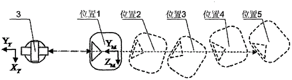
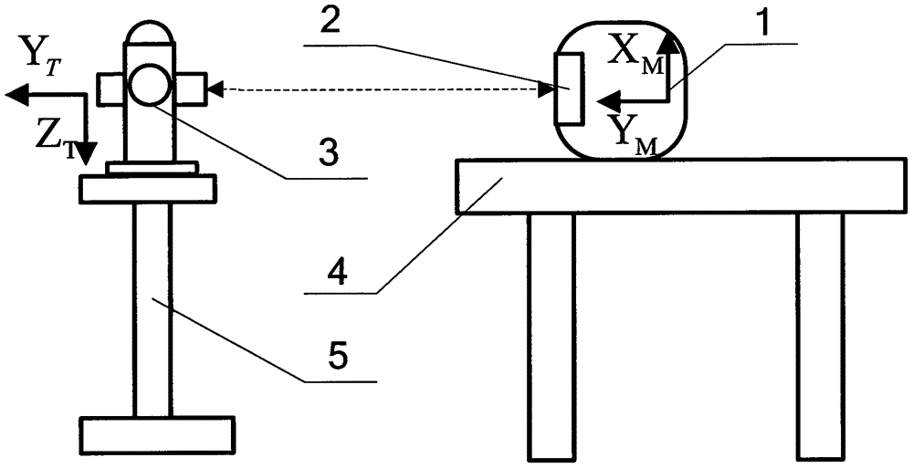
[0053] Step 1: If figure 1 As shown, the inertial group 1 is placed on the platform 4 , the ridge line of the inertial group optical aiming prism 2 is vertical when placed, and the light-transmitting surface faces the autocollimating theodolite 3 . The autocollimating theodolite bracket 5 is erected directly in front of the inertial group optical aiming prism 2, and can be introduced into the position of the north azimuth reference, with a distance of 0.5m-5m. The self-collimating theodolite 3 is fixed on the self-collimating theodolite support 5, adjusts the self-collimating theodolite support 5 so that the line-of-sight axis of the self-collimating theodolite 3 is equal to the inertial group optical aiming prism 2, and the self-collimating theodolite 3 is accurately carried out Leveling. After the equipment is set up, the cable connected to the iner...


PUM


Abstract

The invention provides a calibration method of inertial unit optical aiming prism installation errors. The calibration method is characterized in that prism lines of the inertial unit optical aiming prism rotate for several positions; a self calibration theodolite and an inertial unit optical aiming prism collimator which are fixed in the one position is used in each position. The relative posture of the inertial unit is provided through inertial navigation solution; the relative posture of the theodolite collimation axis can be obtained through reading and calculation via a dial. According to the initial conditions of the self calibration theodolite and the inertial unit optical aiming prism collimator in each position, a multivariate overdetermined equation including inertial unit optical aiming prism installing error Z0 (deflection quantity) and Y0 (inclination quantity) is built; the installing errors Y0 and Z0 of the inertial unit optical aiming prism can be obtained through solving the multivariate overdetermined equation. The posture in the inertial unit rotationprocess is given through inertial navigation solution; the rotation process can be manually completed on an ordinary platform; the requirements on test equipment is low; the realization is easy; the calibration parameters are comprehensive; high universality is realized.

Description

technical field [0001] The invention belongs to the testing field of inertial measurement unit (abbreviated as inertial unit) and in particular relates to a calibration method for installation error of an inertial unit optical aiming prism. Background technique [0002] The inertial group optical sighting prism is a D II-180° right-angle prism, which is the input and output interface of the inertial group azimuth reference, and is used for the introduction of the azimuth reference during the initial alignment of the inertial navigation system and the output of the inertial azimuth reference result. Due to processing and assembly errors, there must be installation errors in the IMU optical aiming prism, and the installation errors will be transmitted to the introduction and output of the azimuth reference. Therefore, it is necessary to calibrate the installation errors of the IMU optical aiming prisms. Its deduction can only be used. [0003] The traditional calibration meth...

Claims


Application Information

Patent Timeline
Patent Type & Authority Applications(China)
IPC IPC(8): G01C25/00G01C1/06
CPCG01C1/06G01C25/005
Inventor 沈小龙刘明王安迪胡华锋杨道安
Owner THE GENERAL DESIGNING INST OF HUBEI SPACE TECH ACAD
Why Eureka
Try Eureka