
Current Sensor Based on Magnetic Circuit and Magnetic Fluid

A current sensor and magnetic fluid technology, applied in the field of current sensing, can solve the problem of low current measurement sensitivity, avoid birefringence problems, solve the hysteresis loop, improve conversion efficiency and current measurement sensitivity.

Inactive Publication Date: 2019-11-29
HARBIN UNIV OF SCI & TECH
View PDF1 Cites 0 Cited by
  • Summary
  • Abstract
  • Description
  • Claims
  • Application Information

AI Technical Summary

Problems solved by technology

At present, there is a current sensor technology combining magnetic fluid and optical fiber, which can make up for the shortcomings of current sensors based on the Faraday effect and GMM materials. For example, CN 201510423585.2 discloses a current sensor based on magnetic fluid. However, the current sensor based on The current measurement sensitivity of the magnetic fluid current sensor is still not high

Method used


Image

  • Current Sensor Based on Magnetic Circuit and Magnetic Fluid
  • Current Sensor Based on Magnetic Circuit and Magnetic Fluid
  • Current Sensor Based on Magnetic Circuit and Magnetic Fluid

Examples


application example 1

[0044] An application example of the current sensor 100 based on the magnetic circuit and the magnetic fluid of the present invention is described below.

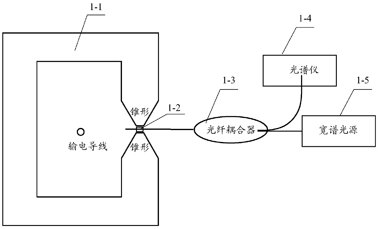
[0045] Such as figure 1 As shown, when the current sensor 100 measures the current, the magnetic conduction circuit 1-1 is set on the measured wire, so that the measured wire passes through the cavity center of the magnetic conduction circuit 1-1, and the magnetic conduction circuit 1-1 is induced to be Measure the current and concentrate the magnetic field generated in the magnetic circuit on the sensor head 1-2. Under the action of a magnetic field, the magnetic fluid will produce a magnetorefractive effect, and its refractive index will change with the change of the magnetic field, which will lead to a change in the optical path of the fiber microcavity, thereby causing the interference spectrum of the fiber microcavity to translate. By detecting the interference spectrum The magnitude of the translation can obtain the ...

application example 2

[0055] An application example for making the sensor head of the present invention is described below.

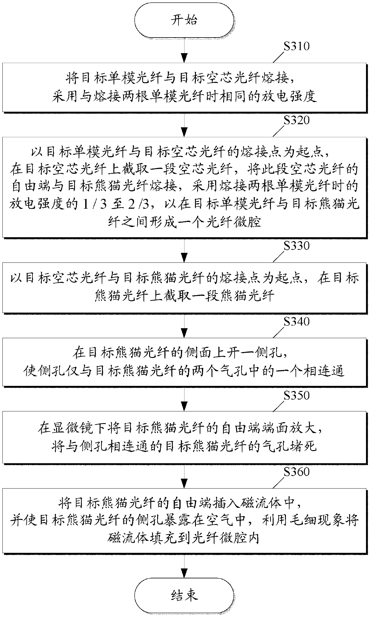
[0056] First, common single-mode fiber (as an example of target single-mode fiber) and hollow-core fiber (as an example of target hollow-core fiber) are fused.

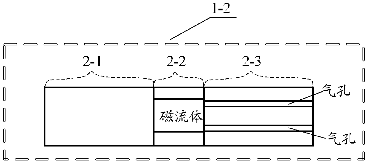
[0057] Then, starting from the fusion point of ordinary single-mode optical fiber and hollow-core optical fiber, cut a section of hollow-core optical fiber with a length between 50 μm and 200 μm on the hollow-core optical fiber, and connect the free end of this section of hollow-core optical fiber to the panda optical fiber (as Example of target Panda fiber) fusion splicing. Among them, the outer diameter of the Panda fiber is the same as that of the ordinary single-mode fiber, which is 125 μm. The diameter of the double hole in the cladding of the Panda fiber is 10 μm-30 μm, and the center-to-center distance of the double hole is 25 μm-60 μm. The discharge intensity used for fusion splicing of hollow core fiber an...


PUM


Abstract

The invention provides a current sensor based on a magnetism-guided loop and a magnetic fluid. The current sensor comprises the magnetism-guided loop, a sensing head, an optical fiber coupler, a spectrometer and a wide spectrum light source. The magnetism-guided loop is a rectangular loop. One side is provided with a slit. Magnetizers of two sides of the slit are two opposite tapers. Top ends of the two tapers are in a round shape. The sensing head is arranged between the top ends of the two tapers. A radial direction of the sensing head is parallel to top end planes of the two tapers. Wide spectrum light emitted by the wide spectrum light source passes through the optical fiber coupler and then enters into the sensing head. A light signal reflected by the sensing head enters into the spectrometer through the optical fiber coupler. By using the above technology of the invention, a birefringence problem based on a Faraday effect current sensor and a hysteresis loop problem based on a super magnetostrictive material current sensor can be avoided; and through a double-taper magnetism-guided loop, magnetic fields generated by measured leads can be gathered to the sensing head so that conversion efficiency from the current to the magnetic field at the sensing head and current measurement sensitivity are greatly increased.

Description

technical field [0001] The invention relates to current sensing technology, in particular to a current sensor based on a magnetic conduction circuit and a magnetic fluid. Background technique [0002] According to the different implementation methods, the current fiber optic current sensors are mainly divided into two categories: (1) Fiber optic current sensors based on the Faraday effect. This sensor has the advantages of good insulation and large measurement range, but there are problems of low fiber Verdet constant and fiber birefringence that are difficult to overcome. (2) Fiber optic current sensors based on giant magnetostrictive materials (GMM). It is difficult for such sensors to overcome the inherent hysteresis nonlinearity of GMM materials, and it is difficult to miniaturize the sensing head. [0003] Magnetic fluid is a kind of superparamagnetic liquid functional material produced in response to the development of modern science. It has almost no hysteresis phen...

Claims


Application Information

Patent Timeline
Patent Type & Authority Patents(China)
IPC IPC(8): G01R19/00G01R15/14
CPCG01R15/148G01R19/0092
Inventor 姜久兴杨玉强葛伟杨群
Owner HARBIN UNIV OF SCI & TECH
Learn More