Automatic tracking antenna gain system for long distance directional image transmission

An automatic tracking and directional transmission technology, applied to antennas, antennas, antenna parts and other directions suitable for movable objects, can solve the limitations and influences of UAV operating radius and operation stability, UAV control signals and The image transmission signal is unstable, which affects the efficiency and safety and stability of transmission line fault finding, so as to achieve the effect of expanding the working radius, enhancing the effect and stability

Inactive Publication Date: 2016-08-31
GUANGDONG POWER GRID CORP ZHAOQING POWER SUPPLY BUREAU
View PDF6 Cites 3 Cited by
  • Summary
  • Abstract
  • Description
  • Claims
  • Application Information

AI Technical Summary

Problems solved by technology

[0002] 80% of the lines under the jurisdiction of the power transmission management are located in mountainous areas. Currently, drones are generally used to complete the daily inspection and fault finding of transmission lines. However, the wireless signal of the DJI F550 series drones used in actual work The control distance and image transmission distance are within a radius of 1.7km. The actual flight distance of the drone can only reach a radius of about 700m. If it exceeds this range, the control signal and image transmission signal of the drone will be extremely unstable. The radius and operation stability are limited and affected, seriously affecting the efficiency and safety and stability of daily inspection and fault finding work of transmission lines

Method used


Image

  • Automatic tracking antenna gain system for long distance directional image transmission

Examples


Embodiment Construction

[0013] In the following, the present invention will be further described in conjunction with the accompanying drawings and specific embodiments, so as to understand more clearly the technical idea claimed in the present invention.

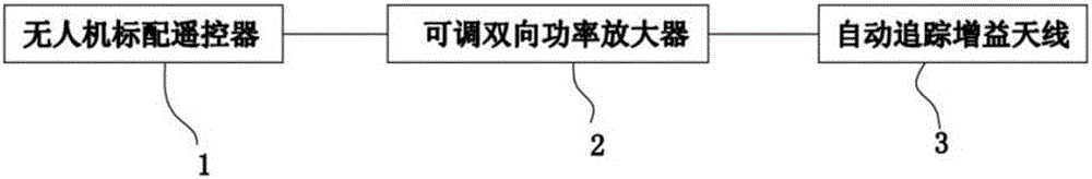
[0014] Such as figure 1 The automatic tracking antenna gain system for long-distance directional transmission of images shown in the present invention includes a standard remote control 1 for drones, an external adjustable two-way power amplifier 2 and an automatic tracking gain antenna 3, and the adjustable two-way power amplifier 2 The signal input end of the UAV is connected to the antenna end signal of the standard remote control 1 of the drone, and the signal output end of the adjustable two-way power amplifier 2 is connected to the automatic tracking gain antenna 3 signal. The auto-tracking booster antenna 3 is an auto-tracking antenna board that can automatically expand and rotate along with the side where the drone's signal is strongest.

...


PUM


Abstract

The invention discloses an automatic tracking antenna gain system for a long distance directional image transmission. The automatic tracking antenna gain system comprises an unmanned plane standard remote controller, an external adjustable bidirectional power amplifier and an automatic tracking gain antenna. The signal input terminal of the adjustable bidirectional power amplifier is in signal connection with the antenna connection terminal of the unmanned plane standard remote controller; the signal output terminal of the adjustable bidirectional power amplifier is in signal connection with the automatic tracking gain antenna; and the automatic tracking gain antenna can automatically extend and retract along with the face of the unmanned plane which has strongest signals. The automatic tracking antenna gain system can effectively expand operating radiuses of the unmanned plane, and enhances the unmanned plane image transmission effect and stability; and the control distance of the unmanned plane and a image transmission distance are more than 2km and the automatic tracking antenna gain system enables the unmanned plane control and the image transmission distance to be not limited by a nominal range.

Description

technical field [0001] The invention relates to the technical field of power transmission line inspection and troubleshooting, in particular to an automatic tracking antenna gain system connected with a standard remote control of a DJI F550 unmanned aerial vehicle. Background technique [0002] 80% of the lines under the jurisdiction of power transmission management are located in mountainous areas. At present, drones are generally used to complete the daily inspection and fault finding of transmission lines. However, the wireless signal of the DJI F550 series drones used in actual work The control distance and image transmission distance are within a radius of 1.7km. The actual flight distance of the drone can only reach a radius of about 700m. If it exceeds this range, the control signal and image transmission signal of the drone will be extremely unstable. The radius and operation stability are limited and affected, which seriously affects the efficiency, safety and stabi...

Claims


Application Information

Patent Timeline
Patent Type & Authority Applications(China)
IPC IPC(8): H01Q23/00H01Q1/32
CPCH01Q23/00H01Q1/3208
Inventor 宋海龙
Owner GUANGDONG POWER GRID CORP ZHAOQING POWER SUPPLY BUREAU
Why Eureka
Try Eureka