
Patsnap Eureka
For R&D, Patsnap Eureka makes reading and utilizing patents & technical documents easy.
Patsnap Eureka AIR
Designed for self-driven R&D workflows. Generate viable solutions, solve complex R&D challenges, empower your innovation with AI.

Patsnap Eureka Materials
Designed for material experts only. Revolutionize your material R&D, from search, analyze, to developing new materials.

TechResearch
Generate reliable direction feasibility study reports for your R&D in just a few steps.

TechSeek
Discover and master advanced knowledge NOW. Basics, ideas, possibilities, all at once.

TechMind
As an expert in R&D Theories, TechMind can generates customized viable solutions instantly.

TechRisk
Analyze your overall solution with one click, know your potential R&D risks in advance.

TechMonitor
Get weekly tech updates, stay abreast of the latest tech innovations and key insights.
Crankshaft solar humidifying and cooling umbrella and using method
A wet wind parasol and solar energy technology, applied in the field of sun umbrellas, can solve the problem that the electric fan cannot directly blow to the umbrella holder, so as to increase the cooling effect, avoid waste and reduce waste
- Summary
- Abstract
- Description
- Claims
- Application Information
AI Technical Summary
Problems solved by technology
Method used
Image

Examples
Embodiment 1
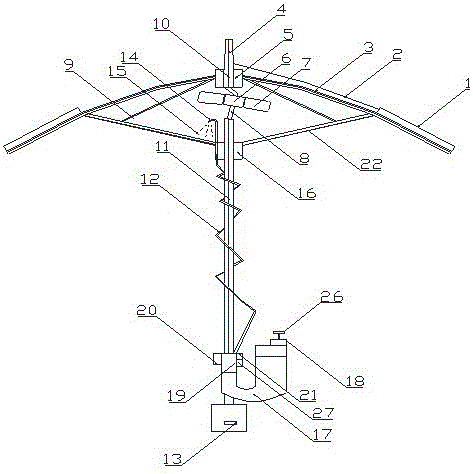
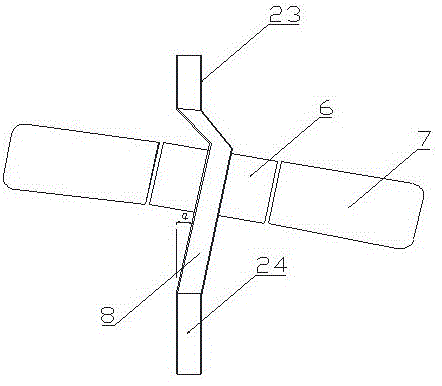
[0033] Such as figure 1 As shown, the first embodiment of the crankshaft solar humidification wind parasol includes an umbrella surface 3, on which a solar battery 1 is fixed, and the electric energy generated by the solar battery 1 enters the hollow inner side of the umbrella handle from the umbrella cap 4 by the wire 2 and connects to the external power supply socket. 13 in parallel, connected in series with the fan motor 6, and connected in series with the atomizing device 19; the fan motor 6 is connected in series with the fan motor power switch 20; the atomizing device 19 is connected in series with the switch 21; The middle section 8 of the crankshaft, the lower section 24 of the hollow crankshaft, the outer rotor 6 of the hollow shaft motor, and the fan 7 fixed on the outside of the outer rotor motor. The upper section 23 of the hollow crankshaft is parallel to the lower section 24 of the hollow crankshaft. The included angle is 10°≤α≤45°, the space inside the upper sec...
Embodiment 2
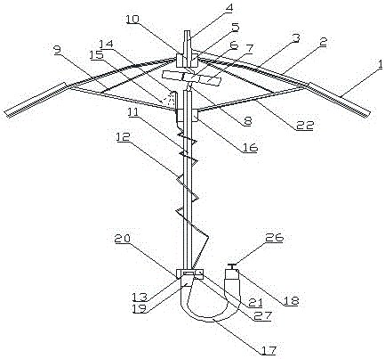
[0043] Such as image 3 Shown is Embodiment 2 of the present invention, wherein the atomizing device 19 is fixed on the lower end of the middle rod 11, the lower end of the atomizing device 19 is connected to the water container 17, the external power socket 13 is fixed on the atomizing device 19, and other structures are the same as those in Embodiment 1 Same, the function of umbrella is identical with embodiment one.
Embodiment 3
[0045] Such as Figure 4 Shown is Embodiment 3 of the present invention, wherein the atomizing device 19 is fixed on the side of the middle rod 11, the lower end of the atomizing device 19 is connected to the water container 17, the water container 17 is fixedly connected to the middle rod 11, and the external power socket 13 is fixed on the atomizing device. On device 19, other structures are identical with embodiment one, and the function of umbrella is identical with embodiment one.
PUM
 Abstract
Description
Claims
Application Information
 - R&D Engineer
- R&D Manager
- IP Professional
- Industry Leading Data Capabilities
- Powerful AI technology
- Patent DNA Extraction
Browse by: Latest US Patents, China's latest patents, Technical Efficacy Thesaurus, Application Domain, Technology Topic, Popular Technical Reports.
© 2024 PatSnap. All rights reserved.Legal|Privacy policy|Modern Slavery Act Transparency Statement|Sitemap|About US| Contact US: help@patsnap.com