
Fine particle rotational flow type electric agglomeration dust removing and collecting device

A fine particle and collection device technology, which is applied in the field of environmental engineering, can solve problems such as human body and environmental hazards, particle size that cannot meet the dust collection requirements, and fine particles that cannot fully collide, so as to improve dust removal efficiency, improve charging effect, The effect of increasing the particle concentration and the number of collisions

Inactive Publication Date: 2016-09-07
CHINA UNIV OF MINING & TECH
View PDF7 Cites 11 Cited by
  • Summary
  • Abstract
  • Description
  • Claims
  • Application Information

AI Technical Summary

Problems solved by technology

A large number of fine particles gather into soot. The existing soot removal methods mainly use dust removal equipment such as electrostatic precipitators, bag filters, and water precipitators. Although these devices have a collection efficiency of Fine particles, the dust removal efficiency is less than 85%, and these fine particles are the cause of great harm to the human body and the environment
In the existing electrocoagulation equipment, the fine particles cannot be fully charged during the charging stage, and during the coagulation process, the fine particles cannot fully collide, so the particle size of the coagulated particles cannot meet the dust collection requirements, resulting in fine particles Dust collection efficiency is low

Method used


Image

  • Fine particle rotational flow type electric agglomeration dust removing and collecting device
  • Fine particle rotational flow type electric agglomeration dust removing and collecting device
  • Fine particle rotational flow type electric agglomeration dust removing and collecting device

Examples


Embodiment Construction

[0015] The present invention will be described in detail below in conjunction with the accompanying drawings.

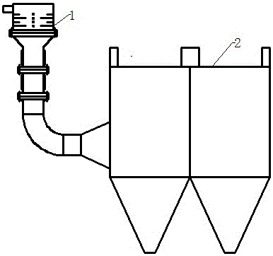
[0016] figure 1 It is a schematic diagram of a fine particle cyclone electrocoagulation and collection device. The electrocoagulation device 1 is located at the front end of the electrostatic precipitator 2. After the fine particles in the smoke are processed by the electrocoagulation device 1, the fine particles are aggregated into smaller particles. Large particles can be collected by electrostatic precipitator 2.

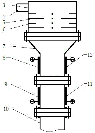
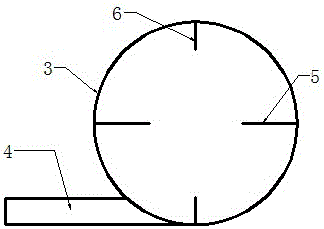
[0017] The electrocoagulation device 1 is installed at the feed port of the electrostatic precipitator 2, and the electrocoagulation device 1 includes a friction charging device and a coagulation device connected in sequence, and the coagulation device is connected with the electrostatic precipitator 1; the friction charging device It includes a shell 3, an airflow particle inlet 4, a prickly electrode 5 with a positive corona and a friction rod 6; the...


PUM


Abstract

The invention discloses a fine particle rotational flow type electric agglomeration dust removing and collecting device. The device is arranged at the front portion of an electric precipitator. Fine particles are carried by airflow to enter a cylindrical shell in the tangential direction. Friction bars and arista electrodes are arranged on the inner wall face of the shell, the particles collide with and make contact with the friction bars to rub electrical charges in the gradual downward rotational flow type moving process, and the arista electrodes intensify the electrical charges under the action of corona. The charged particles enter a pipeline connected through at least one pair of Venturi tubes. High-voltage electrode plates opposite in polarity are arranged on the two sides of the Venturi tubes, consequently, the particles generate collision and coagulation through the action of electric field force in the opposite directions, and the particles are conveyed into the electric precipitator through the pipeline to be collected and subjected to dust removing. The problem that the electrical charges of the fine particles are not sufficient is solved. The collision frequency in the particle coagulation process is increased, particle aggregates with the large granularity can be obtained, the dust removing efficiency of the electric precipitator is improved, the concentration of the fine particles in air is reduced, and the environment pollution is reduced.

Description

technical field [0001] The invention relates to a fine particle swirling electrocoagulation dust removal device, which relates to the technical field of environmental engineering, especially for the removal of inhalable particulate matter in coal-fired dust in thermal power plants, which can obtain better trapping effects and can also be used Dust collection in industrial production to reduce environmental pollution. Background technique [0002] The main source of fine particles is the residues discharged from combustion during daily power generation, industrial production, and vehicle exhaust emissions. Most of them contain toxic substances such as heavy metals, which are harmful to human health and pollute the atmosphere. A large number of fine particles gather into soot. The existing soot removal methods mainly use dust removal equipment such as electrostatic precipitators, bag filters, and water precipitators. Although these devices have a collection efficiency of For ...

Claims


Application Information

Patent Timeline
Patent Type & Authority Applications(China)
IPC IPC(8): B03C3/34B03C3/01
CPCB03C3/01B03C3/34
Inventor 李海生武涛沈子凡刘宇梅玉坤石科军刁瑞姜金乌陈英华
Owner CHINA UNIV OF MINING & TECH
Learn More