
Magnetic carrier and two-component developer

a technology of magnetic carrier and developer, applied in the field of magnetic carrier and two-component developer, can solve the problems of deterioration of developer, prone to occur, and deterioration of developer, so as to prevent image density variations and stable charge-providing performance

Active Publication Date: 2015-06-16
CANON KK
View PDF68 Cites 42 Cited by
  • Summary
  • Abstract
  • Description
  • Claims
  • Application Information

AI Technical Summary

Benefits of technology

[0012]The present invention provides a magnetic carrier and a two-component developer that exhibit a stable charge-providing performance on a long-term basis even under high-stress conditions of use, for example, in a high-speed copier. The present invention also provides a magnetic carrier and a two-component developer that can inhibit the generation of blank dots in a low-humidity environment.
[0016]Image density variations can be prevented because the magnetic carrier according to the present invention has a stable charge-providing performance on a long-term basis even under high-stress conditions of use, for example, in a high-speed copier. The generation of blank dots in a low-humidity environment can also be inhibited.

Problems solved by technology

However, the high density and large saturation magnetization that occur in this case result in a rigid magnetic brush, and as a consequence deterioration of the developer, i.e., the generation of spent carrier and external additive deterioration for the toner, is prone to occur.
However, when the saturation magnetization of an Mg-type ferrite is increased, the resistance then declines and as a consequence it has been quite difficult to optimize both the magnetization and the resistance.
However, the developing performance has been inadequate when used in high-speed devices (50 sheets / minute or more) and during durability testing the image density has undergone variation and / or blank dots have been produced.
However, the amount of charge on the toner readily assumes excessive levels in high-speed devices and there is still room for improvement.

Method used


Image

  • Magnetic carrier and two-component developer
  • Magnetic carrier and two-component developer
  • Magnetic carrier and two-component developer

Examples


examples

[0150]Specific examples of the present invention are described below, but the present invention is not limited to these examples. Unless specifically indicated otherwise, the number of parts and % in the examples and comparative examples are on a mass basis in all instances.

[0151]

[0152]Step 1 (Weighing / Mixing Step):

[0153]

Fe2O387.9mass %Mg(OH)211.1mass %SrCO31.0mass %

[0154]The ferrite starting materials were weighed out so the preceding materials were in the compositional ratio given above. This was followed by pulverization / mixing for 5 hours with a dry vibrating mill using stainless steel beads having a diameter of ⅛ inch.

[0155]Step 2 (Presintering Step):

[0156]The obtained pulverized material was made into approximately 1 mm square pellets using a roller compactor. The coarse particles were removed from these pellets using a vibrating sieve with an aperture of 3 mm and the fines were then removed using a vibrating sieve with an aperture of 0.5 mm. This was followed by sintering for...


PUM

PropertyMeasurementUnit
pore diameteraaaaaaaaaa

Abstract

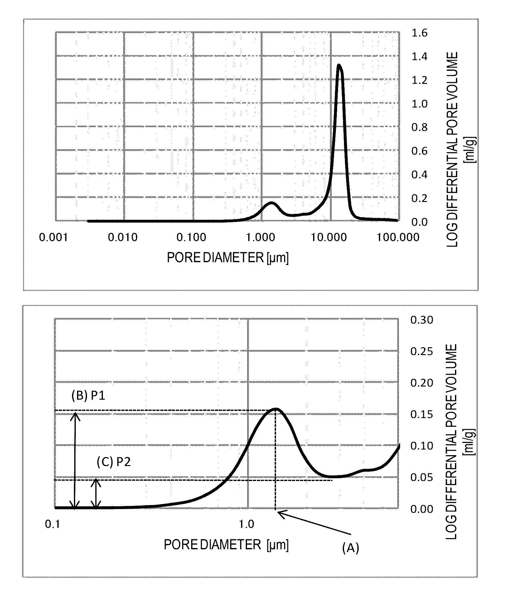
A magnetic carrier having a resin-containing ferrite particles each containing a porous ferrite core and a resin in pores of the porous ferrite core, wherein the porous ferrite core has a particular pore diameter corresponding to the maximum logarithmic differential pore volume in a pore diameter range from at least 0.10 μm to not more than 3.00 μm, the resistivity of the porous ferrite core is in a particular range, and the porous ferrite core contains an oxide of Mg in a particular amount and contains a particular amount of a oxide of at least one metal selected from the group consisting of Mn, Sr, and Ca.

Description

BACKGROUND OF THE INVENTION[0001]1. Field of the Invention[0002]The present invention relates to a magnetic carrier and a two-component developer that are used in electrophotographic systems, electrostatic recording systems, and electrostatic printing systems.[0003]2. Description of the Related Art[0004]The developing systems used in, for example, electrophotography, include monocomponent developing systems, which use only toner, and two-component developing systems, which use a mixture of toner with a magnetic carrier.[0005]Two-component developing systems, because they use a magnetic carrier, have an excellent ability to triboelectrically charge the toner and offer the advantages over monocomponent developing systems of more stable charging characteristics and better long-term maintenance of a high image quality. In addition, two-component developing systems provide an excellent performance with regard to supplying toner to the developing zone and in particular are frequently used...

Claims


Application Information

Patent Timeline
Patent Type & Authority Patents(United States)
IPC IPC(8): G03G9/107G03G9/113H01F1/01G03G9/083
CPCG03G9/0833G03G9/107G03G9/1075H01F1/01G03G9/1131G03G9/1085
Inventor KOMATSU, NOZOMUKAMAE, KENTAROISHIGAMI, KOHBABA, YOSHINOBU
Owner CANON KK
Learn More