Storage apparatus and its control method

a storage apparatus and control method technology, applied in the direction of liquid/fluent solid measurement, sustainable buildings, instruments, etc., can solve the problems of increasing the cost amount of the storage apparatus by a cost amount of the mounted large-capacity battery, the loss of data in the cache memory, and the limited capacity of the battery, so as to increase the charge capacity of the battery for supplying electric power to a volatile memory and a nonvolatile memory, and increase the power source capacity

Inactive Publication Date: 2012-06-21
HITACHI LTD
View PDF9 Cites 43 Cited by
  • Summary
  • Abstract
  • Description
  • Claims
  • Application Information

AI Technical Summary

Benefits of technology

[0016]According to this invention, the charge capacity of a battery for supplying electric power to a volatile memory and a nonvolatile memory can be increased without increasing the power source capacity.

Problems solved by technology

However, since the cache memory is often composed of a volatile memory, if power supply from a power source to the cache memory stops due to, for example, a power failure, data in the cache memory sometimes may sometimes be loss.
However, if the large-capacity battery is mounted in the storage apparatus, the cost of the storage apparatus increases by a cost amount of the mounted large-capacity battery.
Also, even if the large-capacity battery is used, the capacity of the battery is limited.
So, if the power interruption duration due to the power failure increases, there may be no other choice but the data in the cache memory may be destroyed and the business activities may have to be stopped.

Method used


Image

  • Storage apparatus and its control method
  • Storage apparatus and its control method
  • Storage apparatus and its control method

Examples


first embodiment

[0038]This embodiment is designed so that prior to execution of processing for returning information stored in a nonvolatile memory to a shared memory and data stored in the nonvolatile memory to a cache memory at the time of power recovery of a power source, an activation target unit, which is to be activated, from among a plurality of units belonging to a control unit is selected and activated, so that power consumption by the entire storage apparatus is reduced than a case where all the units are activated, thereby producing surplus power from the power source, increasing a charge capacity of a battery by means of the surplus power, and reducing charge time for the battery.

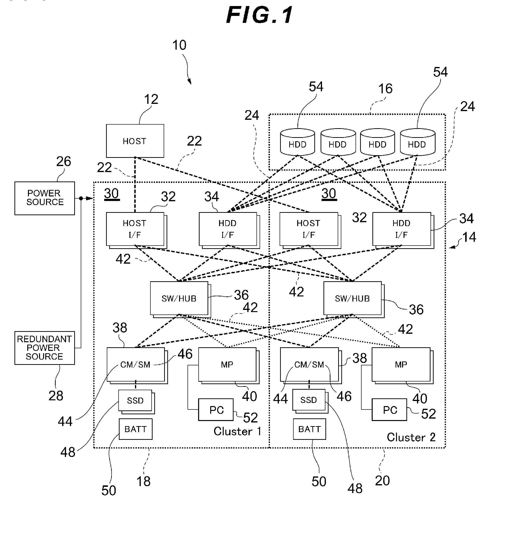
[0039]FIG. 1 is a block configuration diagram of a storage system to which the present invention is applied. Referring to FIG. 1, a storage system 10 includes a host computer 12 and a storage apparatus (storage subsystem) 14.

[0040]The storage apparatus 14 includes a storage device 16 and a plurality of clusters...

second embodiment

[0151]This embodiment is designed to control the activation of each unit by dividing it into a plurality of states and control the charging current for the battery according to each state.

[0152]Specifically speaking, in the process of activating each unit, the activation of each unit can be controlled by dividing it along the time axis into an initialization state (state 1), self-diagnostic state (state 2), a standby state (state 3) in which I / O processing (data input / output processing) is not performed, and an I / O processing state (state 4) in which I / O processing is performed, as shown in FIG. 14.

[0153]So, the main controller 66 controls the activation of each unit by dividing it into four states and monitors the status of each unit. Under this circumstance, the main controller 66 previously calculates the power consumption by each unit in each state (from state 1 to state 4) and stores each calculation result in the status management table in the memory 68.

[0154]Next, FIG. 15 sho...

third embodiment

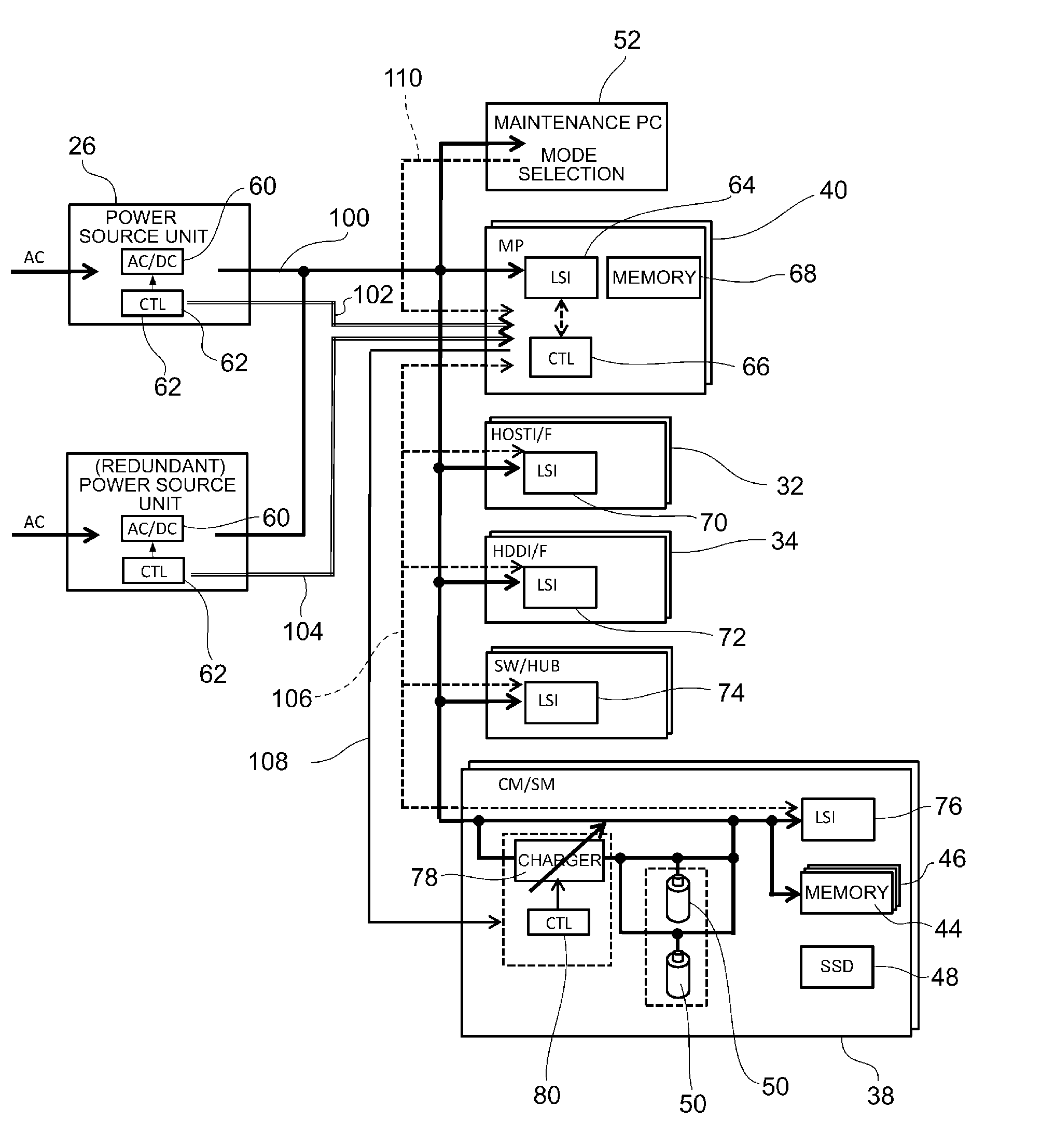
[0181]This embodiment is designed to increase the charging current for the battery 50 based on surplus power produced and obtained by using the redundant power source unit 28 which is the redundant power source.

[0182]The redundant power source such as the redundant power source unit 28 is usually used when abnormality occurs in the power source unit 26. A case where the power source unit 26 and the redundant power source unit 28 are prepared in a one-to-one combination is called a one-to-one redundant configuration; and a case where one redundant power source is prepared as a spare for a plurality of main power sources is sometimes called a n+1 redundant configuration. If the one-to-one redundant configuration or the n+1 redundant configuration is adopted, the charging current for the battery 50 can be increased by using the power source capacity by the redundant power source.

[0183]Under the above-described circumstance, even in a case where abnormality occurs in any of the power so...


PUM


Abstract

The charge capacity of a battery for supplying electric power to a volatile memory and a non-volatile memory is increased without increasing the power source capacity.
A control unit for controlling data input/output processing on a storage device is configured by combining a plurality of units which become load on a power source; and at the time of power interruption of a power source, the control unit saves data and information, which are stored in a volatile memory, to a nonvolatile memory. A battery charged by the power source supplies electric power to the volatile memory and the nonvolatile memory at the time of the power interruption. When the electric power is supplied from the power source to the control unit at the time of power recovery after the power interruption, a main controller selects an activation target unit, which is to be activated, from among the plurality of units belonging to the control unit and controls activation of the selected activation target unit. A battery controller controls a charging current supplied to the battery based on surplus power indicating a difference between total power consumption by the selected activation target unit and a capacity of the power source.

Description

TECHNICAL FIELD [0001]The present invention relates to a storage apparatus having a function that saves data stored in a volatile memory to a nonvolatile memory at the time of power interruption and returns the data stored in the nonvolatile memory to the volatile memory and resumes business activities at the time of power recovery; and a method for controlling such a storage apparatus.BACKGROUND ART [0002]A storage apparatus includes a cache memory for temporarily storing data. In response to a write access from a host computer to a disk drive, the storage apparatus writes write data to the cache memory, upon which it notifies the host computer of the completion of write processing; and in response to a read access from the host computer to the disk drive, the storage apparatus reads data from the cache memory on condition that the read data has a cache hit. As a result, high-speed access is realized.[0003]However, since the cache memory is often composed of a volatile memory, if p...

Claims


Application Information

Patent Timeline
Patent Type & Authority Applications(United States)
IPC IPC(8): G06F1/26
CPCG06F1/3212G06F1/3268Y02B60/1292H02J7/0047Y02B60/1246G06F11/1441Y02D10/00
Inventor HOSAKA, FUMIAKI
Owner HITACHI LTD
Why Eureka
Try Eureka