
A self-excited oscillation high-efficiency atomization device driven by ultrasonic airflow

An atomization device and self-excited oscillation technology, which is applied in the direction of spraying devices, liquid spraying devices, etc., can solve the problems that the atomization cannot meet the fine requirements, the acceleration of water flow is not sufficient, the effect of turbulent water flow is not strong, etc., and achieve water mist coverage The effect of large range, low noise and simple structure

Active Publication Date: 2018-10-30
TAIYUAN UNIV OF TECH
View PDF8 Cites 0 Cited by
  • Summary
  • Abstract
  • Description
  • Claims
  • Application Information

AI Technical Summary

Problems solved by technology

[0003] Chinese patent CN104014096A "A straight-through double-helix convergent water pressure atomizing nozzle" designed a structure that uses the inner surface spiral to cooperate with the water flow pressure to achieve atomization. The cost performance is high, but the overall water flow acceleration is not sufficient, and the atomization reaches Less than fine requirements
Chinese patent CN103115359A "a gas-assisted atomizing nozzle for atomizing high-viscosity liquid" uses a large number of air holes to drain and promote the structure of the atomized liquid. Aids in the atomization of liquids
Chinese patent CN102527567A "An Ultrasonic Atomization Dust Reduction Nozzle for Underground Coal Mine" designed a device that uses the ultrasonic wave formed by the airflow to act on the surrounding liquid and atomize the liquid, and successfully realized the ultrasonic atomization, but the water flow The turbulence effect is not strong, and the atomization is not uniform enough

Method used


Image

  • A self-excited oscillation high-efficiency atomization device driven by ultrasonic airflow
  • A self-excited oscillation high-efficiency atomization device driven by ultrasonic airflow
  • A self-excited oscillation high-efficiency atomization device driven by ultrasonic airflow

Examples


Embodiment 1

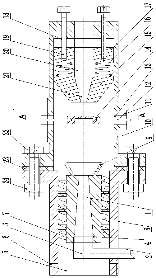
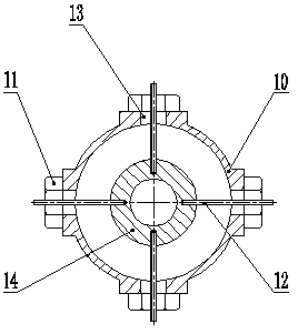
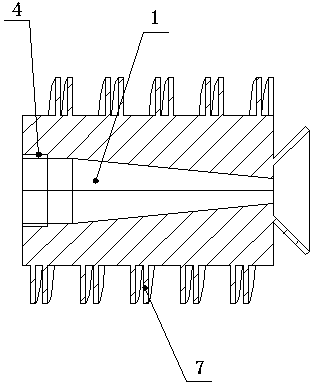
[0022] like Figure 1~3 As shown, a self-excited oscillation high-efficiency atomization device driven by ultrasonic airflow, including a liquid-gas introduction shell (8) and a liquid-gas oscillation shell (10), a liquid-gas introduction shell (8) and a liquid-gas oscillation shell The body (10) is connected; the interior of the liquid gas introduction shell (8) is provided with a spiral water flow introduction valve (7), and the center of the spiral water flow introduction valve (7) is provided with an air flow tapering channel (1), and the spiral water flow introduction valve (7) ) is provided with a spiral groove on the outer wall, and the spiral water flow inlet valve (7) cooperates with the liquid-gas inlet shell (8) in a gap; the side of the liquid-gas inlet shell (8) is provided with an airflow conduit (3), and the airflow tapered channel ( 1) It is connected with the airflow conduit (3) through threads, and the other side of the airflow conduit (3) is connected to the...


PUM


Abstract

The invention discloses a water flow self-oscillation efficient atomization device under push of ultrasonic air flow, which comprises a liquid and gas leading-in shell and a liquid and gas oscillation shell, wherein a spiral water flow leading-in valve is arranged in the liquid and gas leading-in shell, an air flow decreasing channel is arranged at the center of the spiral water flow leading-in valve, and a spiral groove is arranged on the outer wall of the spiral water flow leading-in valve; an air flow guide tube is arranged at one side of the liquid and gas leading-in shell, and the air flow decreasing channel is connected with the air flow guide tube; an air flow ultrasonic oscillation cavity is formed in the liquid and gas oscillation shell; and a water mist leading-out channel is arranged on a tail bottom plate of the liquid and gas oscillation shell, an oscillation baffle plate is connected with a water flow oscillation generating block through a spring, and a water mist increasing channel is arranged in the water flow oscillation generating block. The device has no need of being provided with power machinery parts and external power sources thereof and has the advantages of being good in spray atomization effect, large in water mist coverage area, easy to control and adjust, convenient to use, relatively small in noise and safe and reliable in working.

Description

technical field [0001] The invention relates to a water flow self-excited oscillation high-efficiency atomization device driven by an ultrasonic airflow, in particular to a high-efficiency atomization device applying the principle of self-excited vibration under the action of airflow. Background technique [0002] As the requirements for fine processing are getting higher and higher, the fine dust generated in some processing fields seriously affects the health of workers, and floating into the air will also have a great impact on people's basic life. For the settlement of respirable dust, the atomization efficiency of ordinary nozzles is far from meeting the requirements, and nozzles with higher atomization efficiency are needed to obtain finer water mist to achieve dust settlement control. At present, in order to obtain fine water mist, countries are actively introducing high-tech means, and the methods adopted are mostly pressure atomization, self-excited oscillation atom...

Claims


Application Information

Patent Timeline
Patent Type & Authority Patents(China)
IPC IPC(8): B05B17/06
CPCB05B17/06
Inventor 刘萍李文斌聂勇张琳林晓龙肖星辰刘邱祖林子祥李叶文
Owner TAIYUAN UNIV OF TECH
Learn More