Split combination type solid-liquid separation structure for kitchen waste
A technology for separation of kitchen waste and solid-liquid, which is applied in the field of waste separation, and can solve the problems of splash pollution of kitchen waste, inability to meet the design requirements of kitchen waste separation equipment, and residue cover.
Inactive Publication Date: 2016-09-07
HUIZHOU HENGLIDA IND DEV
9 Cites 0 Cited by
AI-Extracted Technical Summary
Problems solved by technology
In the traditional kitchen waste separation equipment, there is no automatic feeding design at present. The biggest problem is the splash pollution of kitchen waste and the cover of residue, ...
Method used
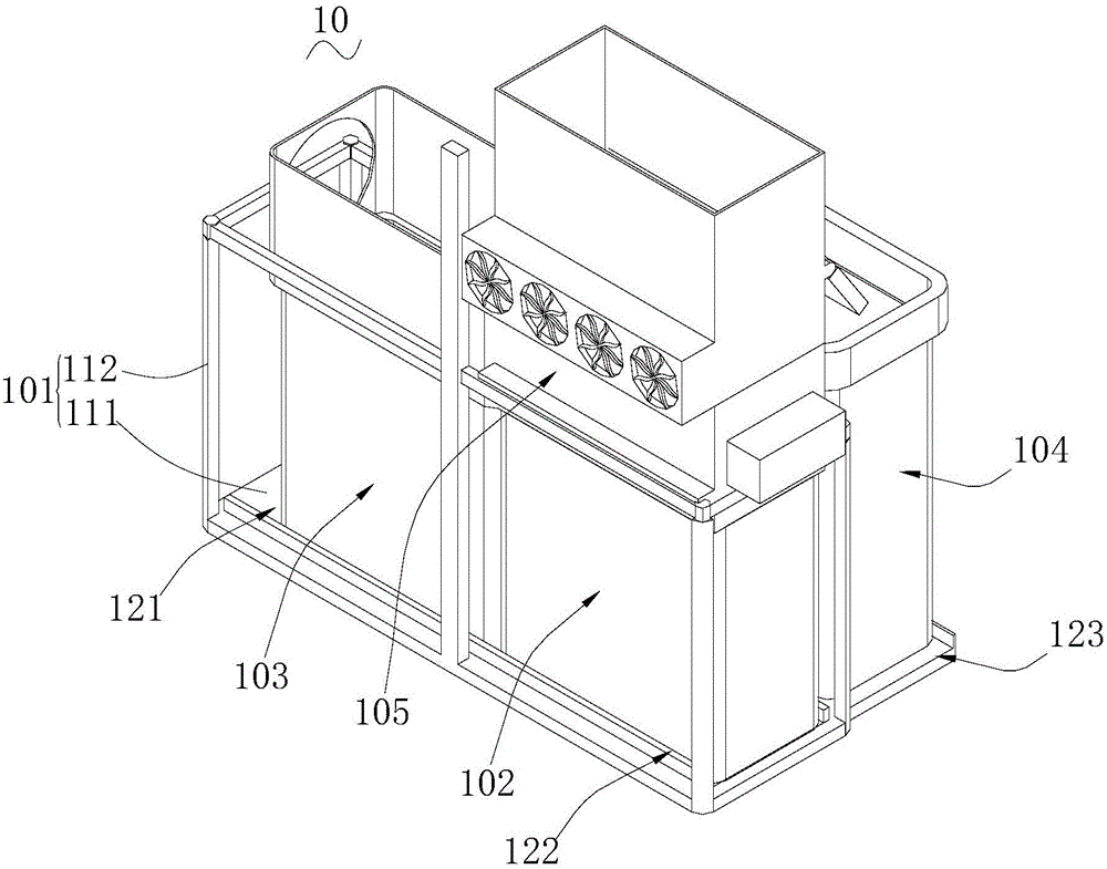
Above-mentioned split combined type kitchen waste solid-liquid separation structure 10, through successively adjacent liquid collection device 102, collection device 103, table paper recovery device 104, by the processing device that is arranged on the liquid collection device 102 105 performs solid-liquid separation of kitchen waste and separates paper-like objects from solids, and sends the liquid into the liquid collection device 102, the solid into the collection device 103, and the paper-like objects into the table paper recycling The device 104 intelligently completes the separation of kitchen waste, effectively preventing the kitchen waste from splashing and polluting the environment.
[0044] In one embodiment, for ease of assembly and use, several support columns 114 and several beams 115 are detachably connected to each other. For example, the support column 114 and the crossbeam 115 are fixed by clamping. Further, on the basis of clamping connection, screw connection is added between the support column 114 and the crossbeam 115, so as to improve the stability of the connection.
[0048] In one embodiment, the liquid collecting device 102 is provided with a first slideway, and the first slideway is slidably connected with the second slideway. The first slideway is provided with a plurality of first limiting grooves, the second slideway is provided with a plurality of first limiting bars, and each first limiting bar is correspondingly accommodated in a first limiting groove. Further, the first limiting bar is an arc-shaped protrusion, and the first limiting groove is an arc-shaped groove. Such setting can make it possible to adjust the orientation of the liquid collecting device 102 through the sliding connection and cooperation betwee...
Abstract
A split combination type solid-liquid separation structure for kitchen waste comprises a frame body, a liquid collection device, a material collection device, a paper napkin recovery device and a treatment device, wherein the frame body comprises a bottom plate and a supporting frame, the supporting frame is arranged on the bottom plate, and a first mounting region, a second mounting region and a third mounting region which are adjacent to one another in sequence are formed by the supporting frame and the bottom plate; the liquid collection device is arranged in the second mounting region; the material collection device is arranged in the third mounting region; the paper napkin recovery device is arranged in the first mounting region; and the treatment device is arranged on the liquid collection device and communicates with the liquid collection device, the material collection device and the paper napkin recovery device. According to the split combination type solid-liquid separation structure for the kitchen waste, under treatment of the treatment device, through the liquid collection device, the material collection device and the paper napkin recovery device which are adjacent to one another in sequence, liquid is delivered into the liquid collection device, solids are conveyed into the material collection device, and paper-like objects are conveyed into the paper napkin recovery device; and the separation work of the kitchen waste is completed intelligently, the kitchen waste is prevented from splashing effectively, and pollution to the environment is avoided.
Application Domain
Solid waste disposal
Technology Topic
Paper sheetPollution +1
Image
Examples
- Experimental program(1)
Example Embodiment
[0033] In order to make the above-mentioned objectives, features and advantages of the present invention more obvious and understandable, the specific embodiments of the present invention will be described in detail below with reference to the accompanying drawings. In the following description, many specific details are explained in order to fully understand the present invention. However, the present invention can be implemented in many other ways different from those described herein, and those skilled in the art can make similar improvements without departing from the connotation of the present invention. Therefore, the present invention is not limited by the specific embodiments disclosed below.
[0034] In the description of the present invention, it should be understood that the terms "center", "longitudinal", "transverse", "length", "width", "thickness", "upper", "lower", "front", " "Back", "Left", "Right", "Vertical", "Horizontal", "Top", "Bottom", "Inner", "Outer", "Clockwise", "Counterclockwise", "Axial" , "Radial", "Circumferential", etc. indicate the orientation or positional relationship based on the orientation or positional relationship shown in the drawings, and are only for the convenience of describing the present invention and simplifying the description, rather than indicating or implying the pointed device or The element must have a specific orientation, be constructed and operated in a specific orientation, and therefore cannot be understood as a limitation of the present invention.
[0035] In addition, the terms "first" and "second" are only used for descriptive purposes, and cannot be understood as indicating or implying relative importance or implicitly indicating the number of indicated technical features. Therefore, the features defined with "first" and "second" may explicitly or implicitly include at least one of the features. In the description of the present invention, "a plurality of" means at least two, such as two, three, etc., unless otherwise specifically defined.
[0036] In the present invention, unless otherwise clearly defined and defined, the terms "installed", "connected", "connected", "fixed" and other terms should be understood in a broad sense, for example, it can be a fixed connection or a detachable connection. , Or integrated; it can be mechanically connected or electrically connected; it can be directly connected or indirectly connected through an intermediary, it can be the internal communication of two components or the interaction relationship between two components, unless otherwise specified The limit. For those of ordinary skill in the art, the specific meanings of the above terms in the present invention can be understood according to specific circumstances.
[0037] In the present invention, unless expressly stipulated and defined otherwise, the first feature “on” or “under” the second feature may be in direct contact with the first and second features, or the first and second features may be indirectly through an intermediary. contact. Moreover, the "above", "above" and "above" of the first feature on the second feature may mean that the first feature is directly above or obliquely above the second feature, or it simply means that the level of the first feature is higher than the second feature. The “below”, “below” and “below” of the second feature of the first feature may mean that the first feature is directly below or obliquely below the second feature, or it simply means that the level of the first feature is smaller than the second feature.
[0038] It should be noted that when an element is referred to as being "fixed to" or "disposed on" another element, it may be directly on the other element or a central element may also be present. When an element is considered to be "connected" to another element, it can be directly connected to the other element or an intermediate element may be present at the same time. The terms "vertical", "horizontal", "upper", "lower", "left", "right" and similar expressions used herein are for illustrative purposes only and do not mean the only implementation.
[0039] See figure 1 , Which is a schematic structural diagram of a split combined food waste solid-liquid separation structure in an embodiment. The split combined food waste solid-liquid separation structure 10 includes: a frame 101, a liquid collecting device 102, and a collecting device 103. A paper recycling device 104 and a processing device 105.
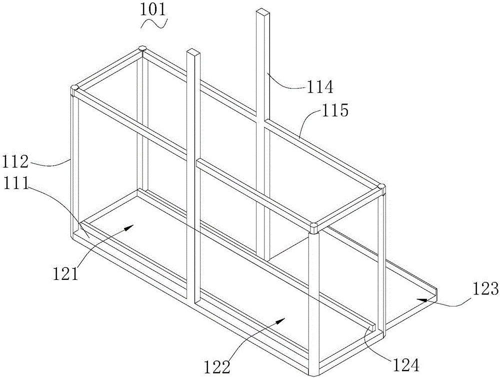
[0040] The frame body 101 includes a bottom plate 111 and a bracket 112. The bracket 112 is disposed on the bottom plate 111. The bracket 112 and the bottom plate 111 form a first installation area 121, a second installation area 122, and a third installation area 123 that are adjacent to each other in sequence. The liquid collection device 102 is disposed in the second installation area 122. The collecting device 103 is arranged in the third installation area 123. The paper recycling device 104 is installed in the first installation area 121.
[0041] The processing device 105 is arranged on the liquid collecting device 102 and is respectively connected with the liquid collecting device 102, the collecting device 103 and the paper recovery device 104. The processing device 105 is used to separate the food waste poured into the processing device 105 into solid-liquid and correspondingly send the liquid to the liquid collecting device 102, the solid to the collecting device 103, and the paper to the paper for paper recycling. 装置104。 Device 104.
[0042] The above-mentioned split and combined food waste solid-liquid separation structure 10 passes through the liquid collecting device 102, the collecting device 103, and the paper recovery device 104 that are adjacent to each other in sequence, and the food is processed by the processing device 105 provided on the liquid collecting device 102. The solid-liquid separation of kitchen waste and the separation of the paper in the solid, and the liquid is sent to the liquid collecting device 102, the solid is sent to the collecting device 103, and the paper is sent to the paper recovery device 104, respectively. Intelligently complete the separation of food and kitchen waste, effectively preventing the splashing of food and kitchen waste and polluting the environment.
[0043] See figure 2 , Which is a schematic structural diagram of the frame body 101 in an embodiment. The figure shows a first installation area 121, a second installation area 122, and a third installation area 123 formed by the bracket 112 and the bottom plate 111, which are sequentially adjacent. The bracket 112 is a frame structure and has a plurality of support columns 114 and a plurality of beams 115. A number of support columns 114 are respectively arranged at the two ends and the middle of the bottom plate 111. A plurality of beams 115 are arranged at one end of the plurality of supporting columns 114 away from the bottom plate 111.
[0044] In one embodiment, in order to facilitate assembly and use, a plurality of support columns 114 and a plurality of beams 115 are detachably connected to each other. For example, the support column 114 and the cross beam 115 are fixed by a snap connection. Further, the support column 114 and the cross beam 115 are fixed in a snap-fitting manner by adding a screw connection method to improve the stability of the connection.
[0045] In this embodiment, the plurality of support pillars 114 include a plurality of first support pillars, a plurality of second support pillars, and a plurality of third support pillars. The first end of the bottom plate 111 is provided with two first mounting holes, and two first supporting columns are respectively provided. The second end of the bottom plate 111 is provided with two second mounting holes, and two second supporting posts are respectively provided. Two third mounting holes are provided in the second middle area of the bottom plate 111 and two third support posts are respectively provided. The two first support columns and the two third support columns correspondingly form a second installation area 122 with a bottom plate. Correspondingly, the bottom plate between the two second support columns and the two third support columns forms a third installation area 123. The first installation area 121 is adjacent to the second installation area 122. A cross beam is respectively arranged between the two first support columns, between the first support column and the second support column, between the two second support columns, and between the second support column and the third support column.
[0046] Further, the first installation area 121, the second installation area 122 and the third installation area 123 form an L-shaped cross section. This arrangement can be formed with the second installation area 122 as the axis, and the first installation area 121 and the third installation area 123 are arranged around the second installation area 122, so that the paper recycling device 104 and The collecting device 103 arranged on the third installation area 123 is adjacent to the liquid collecting device 102 arranged on the second installation area 122 to collect the separated paper, solid waste and liquid waste respectively, and prevent the separation It is far away and causes the phenomenon of splashing of kitchen waste to occur, which improves the degree of hygiene.
[0047] Further, the first installation area 121 is provided with a first slide rail, the second installation area 122 is provided with a second slide rail, and the third installation area 123 is provided with a third slide rail. For example, the liquid collecting device 102 is slidably arranged in the second installation area 122 via a second slide rail. For example, the collecting device 103 is slidably arranged in the third installation area 123 via a third slide rail. For example, the paper recycling device 104 is slidably arranged in the first installation area 121 via a first slide rail.
[0048] In an embodiment, the liquid collection device 102 is provided with a first slide, and the first slide is slidably connected to the second slide. A number of first limit slots are provided on the first slide, and a number of first limit bars are provided on the second slide rail, and each first limit bar is correspondingly accommodated in a first limit slot. Further, the first limiting bar is an arc-shaped protrusion, and the first limiting slot is an arc-shaped groove. This arrangement can make it possible to improve the orientation of the liquid collecting device 102 through the sliding connection of the first slide rail and the second slide rail and the limiting effect of the first limiting groove on the first limiting bar when installing the liquid collecting device 102 The accuracy of the advancing depth of the frame body 101 also improves the stability of the installation of the liquid collecting device 102 in the second installation area 122.
[0049] In an embodiment, the collecting device 103 is provided with a second slide, and the second slide is slidably connected to the third slide. A number of second limit slots are provided on the second slide rail, and a number of second limit bars are provided on the third slide rail, and each second limit bar is correspondingly accommodated in a second limit slot. Further, the second limiting bar is an arc-shaped protrusion, and the second limiting groove is an arc-shaped groove. This arrangement can make it possible to improve the orientation of the liquid collecting device 102 through the sliding connection of the second slideway and the third slide rail and the limiting effect of the second limiting groove on the second limiting bar when installing the liquid collecting device 102 The accuracy of the advancing depth of the liquid collecting device 102 also improves the stability of the liquid collecting device 102 installed in the third installation area 123.
[0050] In one embodiment, the paper recycling device 104 is provided with a third slide, and the third slide is slidably connected to the first slide. A number of third limit slots are opened on the third slide, and a number of third limit bars are arranged on the first slide rail, and each third limit bar is correspondingly accommodated in a third limit slot. Further, the third limiting bar is an arc-shaped protrusion, and the third limiting groove is an arc-shaped groove. This arrangement can make it possible to adjust the orientation of the liquid collecting device 102 through the sliding connection of the third slideway and the first slide rail and the limiting effect of the third limiting groove on the third limiting bar when installing the liquid collecting device 102 The accuracy of the advancing depth of the liquid collecting device 102 also improves the stability of the liquid collecting device 102 installed in the first installation area 121.
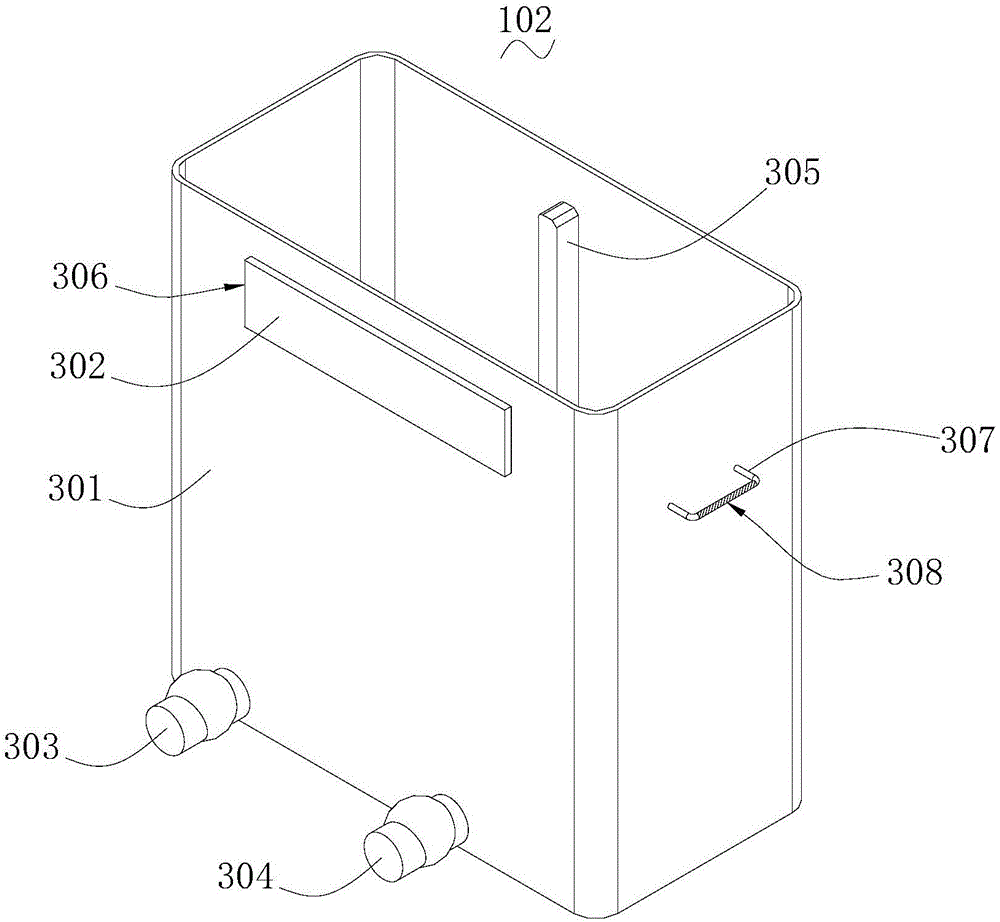
[0051] See image 3 , Which is a schematic diagram of the structure of the liquid collection device 102 in an embodiment. The liquid collection device 102 includes a box 301, a processor 302, and an electronically controlled oil drain ball pump 303, an electronically controlled drain ball pump 304, Liquid level sensor 305. The electronically controlled drain ball pump 303 and the electronically controlled drain ball pump 304 are arranged at the bottom of the tank 301. The liquid level sensor 305 is arranged on the side wall of the box body 301 and is used to detect the change information of the height of the oil-water separation interface in the box body 301. The processor 302 is configured to turn on or off the electronically controlled oil drain ball pump 303 and the electronically controlled drain ball pump 304 according to the change information.
[0052] Further, a mounting position 306 is provided on the outer side wall of the box body 301, and the processor 302 is disposed on the mounting position 306. For example, the liquid collection device 102 further includes a power supply device provided at the installation position 306, and the power supply device is connected to the processor 302 for supplying power to the processor 302. Preferably, the power supply device is a rechargeable lithium battery. For another example, the power supply device has a power plug for connecting an external power source through the power plug.
[0053] Further, a transparent cover is provided on the installation position 306, and the processor 302 is covered by the transparent cover to prevent moisture from entering the processor 302. For example, the transparent cover is made of glass material; in another example, the transparent cover is made of rubber material; in another example, the transparent cover is made of plastic material. For example, a sealed space is formed between the transparent cover and the box body 301, and the processor 302 is disposed in the sealed space.
[0054] In this embodiment, the processor 302 is a single-chip microcomputer, which uses the low voltage and low power consumption of the single-chip microcomputer to increase the working time of the liquid collecting device 102, and at the same time makes the process of producing the box 301 more convenient and reduces the production cost of the enterprise. In other embodiments, the processor 302 may also be other types of processors, such as an ARM series (Advanced RISC Machines, advanced reduced instruction set processor) processor, or DSP (Digital Signal Processing, digital signal processing). Processor, such as SOC processor (System On Chip, embedded system on chip) and so on.
[0055] Further, the bottom of the box body 301 is provided with an oil outlet and a water outlet, the electronically controlled oil drain ball pump 303 is connected to the box body 301 through the oil outlet, and the electronically controlled drain ball pump 304 is connected to the box body 301 through the water outlet. When the electronically controlled oil drain ball pump 303 is turned on, it connects the inside and outside of the tank 301 to pump the oil in the tank 301 to the outside of the tank 301. When the electronically controlled drainage ball pump 304 is turned on, it communicates with the inside and outside of the tank 301 to pump the corrosive water in the tank 301 to the outside of the tank 301.
[0056] It can be understood that since the density of oil is lower than that of water and the oil is above the water, there is an interface between the two. Therefore, the liquid level sensor 305 detects the change information of the interface. When the interface is located at the control oil ball pump 303 When it is above the oil inlet, it is only necessary to turn on the electronically controlled drainage ball pump 304 for drainage. When the interface is located at the oil inlet of the electronically controlled drain ball pump 303, turn off the electronically controlled drain ball pump 304 and turn on the electronically controlled drain ball pump 303 to drain the oil out of the tank 301, thereby achieving oil-water separation and separate collection and processing.
[0057] Further, the box body 301 is a hollow cuboid with one side open. In other embodiments, the box body 301 may also have other shapes and structures, such as a hollow truncated cone with one side open; another example, a hollow cylinder with one side open; another example, a hollow triangular prism with one side open, etc. . It should be pointed out that the shape and structure of the box body 301 only need to be stable and have an opening and a cavity communicating with the opening. The opening is used to communicate with the outside, and the cavity is used to contain the liquid after solid-liquid separation.
[0058] Further, the liquid collection device 102 further includes a handle 307 which is arranged on the box body 301. Preferably, the handle 307 is arranged on the golden section line on the side of the box body 301 to facilitate user operation. Preferably, the handle 307 is arranged obliquely on the side of the box body 301, for example, the handle 307 and the side of the box body 301 are at 30 degrees, and the handle 307 and the side of the box 301 are at 45 degrees. The side is 15 degrees.
[0059] Further, the handle 307 has a smooth surface structure. For example, the handle 307 is rod-shaped; for example, the handle 307 is rod-shaped; for example, the handle 307 is a rectangular parallelepiped shape; for example, the handle 307 is a hemispherical shape.
[0060] Furthermore, the handle 307 is provided with a non-slip part 308. The non-slip portion 308 is made of soft material, for example, made of soft rubber material; for example, it is made of silicone material.
[0061] Further, the anti-skid portion 308 has a number of anti-skid protrusions. Further, a plurality of non-slip protrusions are distributed in a matrix. Further, the outer side wall of the box body 301 is provided with a heating material and a heating wire wrapped by the heating material. For example, the heating material is PI heating film.
[0062] Such as Figure 4 As shown, it is a schematic diagram of the steps of the control method of oil-water separation in an embodiment. Now, a specific control method is used to further explain the control method of oil-water separation:
[0063] Step S401: Obtain a detection instruction.
[0064] Specifically, an infrared sensing device is provided at the opening of the box. The infrared sensing device is electrically connected with the processor. The infrared sensing device is used to detect whether there is an object flowing in the opening of the box. For example, if liquid flows into the box from the opening, it means there is an object flowing. When the infrared sensing device senses that there is an object flowing, it generates a detection instruction and sends the detection instruction to the processor, so that the processor obtains the detection instruction. The detection instruction can also be obtained by touching the handle. For example, a pressure sensor is provided on the handle. When the user holds the handle, the sensor generates a pressure signal by force, sends the pressure signal to the processor, and sets the processor to receive the signal from the pressure sensor as a detection instruction. Therefore, the processor obtains the detection instruction. It can be understood that the purpose of acquiring the detection instruction is to send to the processor the preparation for the detection of the oil-water separation interface, so that the processor can coordinate the work of various devices in the next steps.
[0065] Step S402: According to the detection instruction, detect whether the liquid in the tank has an oil-water separation interface.
[0066] Specifically, after receiving the detection instruction, the processor sends a liquid level detection opening instruction to the liquid level sensor, so that the liquid level sensor works, and judges whether there is an oil-water separation interface in the liquid in the tank. It can be understood that when the liquid continues to enter the box from the opening of the box, the liquid in the box is in a turbid state, and of course there is no oil-water interface at this time. Therefore, after the processor receives the detection instruction, it continuously sends the liquid level detection opening instruction to the liquid level sensor, so that the liquid level sensor continues to work until the liquid in the tank is emptied, the liquid level sensor stops working.
[0067] Step S403: When the oil-water separation interface exists, it is determined whether the distance between the oil-water separation interface and the bottom of the box is a preset distance.
[0068] Specifically, the liquid level sensor continues to work, and continuously feeds back the status information of the oil-water separation interface to the processor. Since the electronically controlled drain ball pump and the electronically controlled drain ball pump are arranged at the bottom of the box, the oil-water separation interface is higher than the water inlet of the electronically controlled drain ball pump or higher than the oil inlet of the electronically controlled drain ball pump, indicating that the box is inside The water can be discharged by the electronically controlled drain ball pump, so when the distance between the oil-water separation interface and the bottom of the tank is greater than the water inlet of the electronically controlled drain ball pump or between the oil inlet of the electronically controlled drain ball pump and the bottom of the tank When the distance between the oil and water separation interface and the bottom of the box body is a predetermined distance, the preset distance is immediately there when the distance between the oil and water separation interface and the bottom of the box body is less than or equal to the water inlet of the electronically controlled drainage ball pump or When the distance between the oil inlet of the electronically controlled oil drain ball pump and the bottom of the box body is not set, the preset distance does not immediately exist between the oil-water separation interface and the bottom of the box body.
[0069] Step S404: If yes, send a first start instruction to start the electronically controlled drainage ball pump.
[0070] Specifically, after the processor receives the status information of the oil-water separation interface from the liquid level sensor, it determines the distance between the oil-water separation interface and the bottom of the tank and the water inlet of the electronically controlled drain ball pump or the electronically controlled oil drain ball. The distance between the oil inlet of the pump and the bottom of the box, when the distance between the oil-water separation interface and the bottom of the box is greater than the water inlet of the electronically controlled drain ball pump or the oil inlet of the electronically controlled drain ball pump and the bottom of the box When the distance between the two, the processor generates a first opening instruction, and sends the first opening instruction to the electronically controlled drainage ball pump. The electronically controlled drainage ball pump works after receiving the first opening command, and drains the water in the box to the outside.
[0071] Step S405: If not, send a second start instruction to start the electronically controlled oil drain ball pump.
[0072] Specifically, after the processor receives the status information of the oil-water separation interface from the liquid level sensor, it determines the distance between the oil-water separation interface and the bottom of the tank and the water inlet of the electronically controlled drain ball pump or the electronically controlled oil drain ball. The distance between the oil inlet of the pump and the bottom of the box, when the distance between the oil-water separation interface and the bottom of the box is less than or equal to the water inlet of the electronically controlled drain ball pump or the oil inlet of the electronically controlled drain ball pump and the tank When the distance between the bottom of the body is determined, the processor generates a second opening instruction and sends the second opening instruction to the electronically controlled drainage ball pump. The electronically controlled drainage ball pump works after receiving the second opening command, and drains the oil in the tank to the outside.
[0073] See Figure 5-1 with Figure 5-2 , Which are respectively a schematic diagram of the structure of the feeding device 501 in one embodiment and a schematic view of the structure from another perspective. In an embodiment, the processing device 105 of the split combined food waste solid-liquid separation structure includes the feeding device 501, The processing device 105 is also used for separating the paper objects in the food waste through the feeding device 501 and sending the paper objects in the food waste to the paper recycling device 104.
[0074] The feeding device 501 includes a fan 510 and a flow guide 511. The guide portion 511 has an input end 512 and an output end 513. The input 512 is the inlet. The deflector 511 is provided at the output end 513 of the feeding device 501, and the deflector 511 has a plurality of partitions 514 for catching paper objects in food waste. The air outlet of the fan 510 faces the diversion part 511, and the opening of the paper recycling device 104 is adjacent to the diversion part 511 for blowing the paper in the plurality of partitions 514 to the paper recycling device 104. For another example, the feeding device 501 includes an image acquisition and recognition unit and a gripping unit, the image acquisition and recognition unit is used to acquire images and identify the table paper, and the gripping unit is used to grip the table paper and send it to the recycling device; for example, The gripping unit is provided with a motor and a mechanical arm, the end of the mechanical arm is provided with a suction head, and the motor is connected to the suction head through a pipe for controlled suction and placement of the table paper.
[0075] Further, a plurality of partitions 514 are distributed in a row. Further, the plurality of partitions 514 are evenly distributed in a row at equal intervals. Further, the distance between two adjacent partitions 514 is 1.5 cm to 3 cm. Further, the distance between two adjacent partitions 514 is 2 cm.
[0076] Furthermore, a number of hooks are provided on the surface of the partition 514 for clamping the paper in the food waste between two adjacent partitions 514. Furthermore, several hooks are distributed on the surface of the partition 514 in a disordered state. Further, the height of the hooks protruding from the surface of the partition 514 is 0.2-0.5 cm.
[0077] In one embodiment, the fan 510 is connected to the processor, and works in a unified manner under the control of the processor.
[0078] See Figure 6-1 with Figure 6-2 , Which is a schematic structural diagram of the pushing device in an embodiment and a structural schematic diagram from another perspective. The processing device 105 further includes a pushing device 601. Combine figure 1 , Figure 5-1 with Figure 5-2 , The pushing device 601 and the feeding device 501 are connected. The pushing device 601 is used for solid-liquid separation of the food waste after the paper is separated, and the liquid after the solid-liquid separation is sent to the liquid collecting device 102 and the solids are sent to the collecting device 103.
[0079] In one embodiment, the pushing device 601 includes a filter element 602 and a pushing element 603. The filter element 602 is arranged at the output end of the pushing device 601. The pushing element 603 is arranged inside the pushing device 601 and on the filter element 602. When working, the food waste in the pushing device 601 is sent from the output end of the pushing device 601 to the collecting device 103.
[0080] Furthermore, the pushing device 601 further includes a motor 604. The motor 604 is connected to the pushing member 603. Used to drive the pusher 603 to rotate. For example, the pushing member 603 has connected rotating blades and a rotating shaft. The rotating shaft is connected to the rotor of the motor 604. When the motor 604 is working, the rotating shaft is driven to rotate by the rotor, so that the rotating blades rotate to remove food waste from the pushing device. The output end of 601 is sent to the collecting device 103.
[0081] Furthermore, the pushing device 601 further includes a housing 605. The housing 605 has a receiving cavity 606. The pushing member 603 is disposed in the accommodating cavity 606. The motor 604 is arranged outside the housing 605.
[0082] Further, the filtering end of the pushing device 601 is in communication with the liquid collecting device 102. The output end of the feeding device 501 is connected with the input end of the pushing device 601, and is used to send food waste into the pushing device 601 and the pushing device 601 to the collecting device 103.
[0083] Further, the guide portion 511 is arranged between the output end of the feeding device 501 and the input end of the pushing device 601.
[0084] Further, the feeding device 501 has an input port for pouring food waste, that is, an input end 512, which is used to separate the paper from the food waste poured from the feed port and send it to the paper for recycling. 装置104。 Device 104.
[0085] Further, the filtering end of the pushing device 601 is in communication with the liquid collecting device 102, and the liquid after solid-liquid separation enters the liquid collecting device 102 along the filtering end of the pushing device 601.
[0086] Further, the output end of the feeding device 501 is communicated with the input end of the pushing device 601, and is used to collect food and kitchen waste and send the food and kitchen waste to the pushing device 601.
[0087] Further, the liquid collecting device 102, the collecting device 103, and the paper recovery device 104 abut in sequence.
[0088] In one embodiment, the motor 604 is connected to the processor, and works in a unified and coordinated manner under the control of the processor.
[0089] See Figure 7 , Which is a schematic diagram of the structure of the aggregate device 103 in an embodiment, and the aggregate device 103 includes a first body 700. The first body 700 has a matching portion 701 and a receiving portion 702. The matching part 701 is matched with the housing 605. For example, the matching portion 701 is provided with a perforation, and the perforation communicates with the containing cavity 606 of the housing 605 to receive food waste from the containing cavity 606. The accommodating part 702 has a cavity that communicates with the matching part 701. After the matching part 701 receives food waste from the accommodating cavity 606, the food waste enters the cavity of the accommodating part 702 to be stored.
[0090] See Figure 8 , Which is a schematic structural diagram of the paper recycling device 104 in an embodiment, and the paper recycling device 104 includes a second body 800. The second body 800 has a receiving cavity 801, and the receiving cavity 801 is adjacent to the input port 512 of the feeding device 501, so as to collect the paper in the food waste through the receiving cavity 801.
[0091] See Picture 9 , Which is a schematic structural diagram of a spray device 901 in an embodiment, and further, the split combined food waste solid-liquid separation structure further includes a spray device 901. Combine figure 1 For example, the output end of the spray device 901 is provided in the processing device 105, and is used to spray high-pressure cleaning liquid into the processing device 105 to clean the residue in the processing device 105.
[0092] The spray device 901 includes a pressure pump 902, a disinfectant tank 903, a clean water tank 904 and a spray head 905. The pressurizing pump 902 is in communication with an external water source 906, and the pressurizing pump 902 is in communication with the spray head 905 through the disinfectant tank 903, and the pressurizing pump 902 is also in communication with the spray head 905 through the clean water tank 904.
[0093] The pressurizing pump 902 communicates with an external water source through the water inlet pipe 907, communicates with the disinfectant tank 903 through the first water inlet pipe 908, and communicates with the clean water tank 904 through the second water inlet pipe 909.
[0094] The disinfectant tank 903 communicates with the spray head 905 through the first water outlet pipe 910, and the clean water tank 904 communicates with the spray head 905 through the second water outlet pipe 911.
[0095] Further, the heating chamber 913 is further included, and the heating chamber 913 is respectively connected with the pressure pump 902 and the clean water chamber 904. The heating chamber 913 is used to heat the clean water from the pressure pump 902, so that the water sprayed by the spray head 905 is high temperature and high pressure clean water. It can be understood that high temperature can remove bacteria to a certain extent, so the use of high temperature and high pressure clean water can cooperate with disinfection The water provides sterilization and disinfection functions for the treatment device 105.
[0096] Further, the heating chamber 913 is in communication with the pressurizing pump 902 through the first heating pipe, and the heating chamber 913 is in communication with the clean water chamber 904 through the second heating pipe.
[0097] Further, it also includes a water inlet valve 914 which is arranged on the water inlet pipe 907. Furthermore, the heating valve 915 is further included, and the heating valve 915 is arranged on the second heating pipe 916.
[0098] Further, it also includes a disinfection valve 917 which is arranged on the first water outlet pipe 910. Furthermore, it also includes a drain valve 918 which is arranged on the second water outlet pipe 911.
[0099] Further, there are two ejection heads 905, and the two ejection heads 905 are arranged oppositely. This arrangement allows the two spray heads 905 to work simultaneously to improve the efficiency of sterilization and disinfection. For example, one of the spray heads 905 sprays clean water of high temperature and high pressure, and the other spray head 905 sprays disinfectant.
[0100] In an embodiment, the pressure pump 902, the spray head 905, the water inlet valve 914, the drain valve 918, and the heating valve 915 are all connected to the processor, and work in a unified and coordinated manner under the control of the processor.
[0101] The technical features of the above-mentioned embodiments can be combined arbitrarily. In order to make the description concise, all possible combinations of the various technical features in the above-mentioned embodiments are not described. However, as long as there is no contradiction in the combination of these technical features, All should be considered as the scope of this specification.
[0102] The above-mentioned embodiments only express several implementation modes of the present invention, and the description is relatively specific and detailed, but it should not be understood as a limitation on the scope of the invention patent. It should be pointed out that for those of ordinary skill in the art, without departing from the concept of the present invention, several modifications and improvements can be made, and these all fall within the protection scope of the present invention. Therefore, the protection scope of the patent of the present invention should be subject to the appended claims.
PUM


Description & Claims & Application Information
We can also present the details of the Description, Claims and Application information to help users get a comprehensive understanding of the technical details of the patent, such as background art, summary of invention, brief description of drawings, description of embodiments, and other original content. On the other hand, users can also determine the specific scope of protection of the technology through the list of claims; as well as understand the changes in the life cycle of the technology with the presentation of the patent timeline. Login to view more.