Combined type blanking female die and assembly method thereof

A combined and blanking technology, applied in the field of mold manufacturing, can solve problems such as mold failure, cracking at corners, complex structure, etc., and achieve the effect of simplifying design and manufacturing, prolonging service life, and expanding the scope of application

Active Publication Date: 2016-09-07
JIANGSU UNIV OF SCI & TECH
View PDF14 Cites 9 Cited by
  • Summary
  • Abstract
  • Description
  • Claims
  • Application Information

AI Technical Summary

Problems solved by technology

At present, the production of conventional square holes in thin plates is formed by die punching. Usually, a set of molds is used for a square hole of one specification, and the concave and convex molds are usually integral, that is, the concave and convex molds are composed of one part. The corners of the die die are sharp corners. During the process of machining and heat treatment, stress concentration is likely to occur at the sharp corners, causing cracks at the corners and making the mold invalid.
Therefore, the existing one-piece blanking die with square holes can only be used in one-to-one correspondence, and the corners of the die are prone to stress concentration, resulting in high cost of use of the die
[0003] In addition, in the manufacturing process of the square hole integral blanking die, because the consumed mold material is relatively large in volume and the manufacturing process is complicated, the manufacturing cost of the mold is high
[0004] Check the Chinese patent, a large insert type blanking die, patent number: 201110256148.8, this die is to divide the large die into several sections, install it on the die holder, and form a whole die, which solves the problem of the single volume of the die material It is a big problem, but a set of mold inserts can only be assembled into a mold of one specification, and its structure becomes more complicated. In the normal use process, there is no obvious difference from the ordinary integral die, neither can significantly improve The service life of the mold cannot be extended, nor can it expand its application range

Method used


Image

  • Combined type blanking female die and assembly method thereof
  • Combined type blanking female die and assembly method thereof
  • Combined type blanking female die and assembly method thereof

Examples


Embodiment Construction

[0029] In order to make the purpose and technical solution of the present invention more clear, the technical solution of the present invention will be further described below in conjunction with the accompanying drawings.

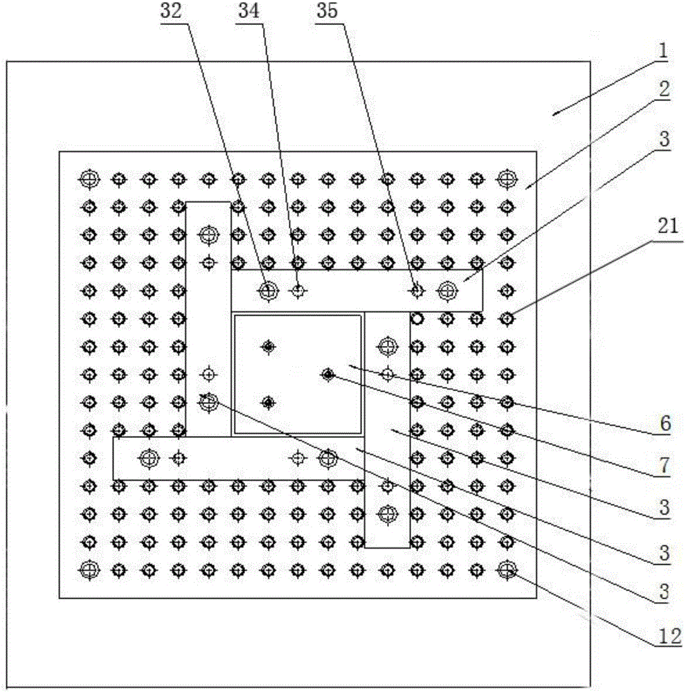
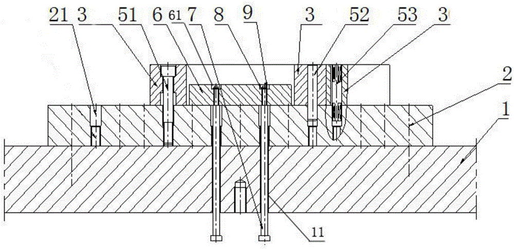
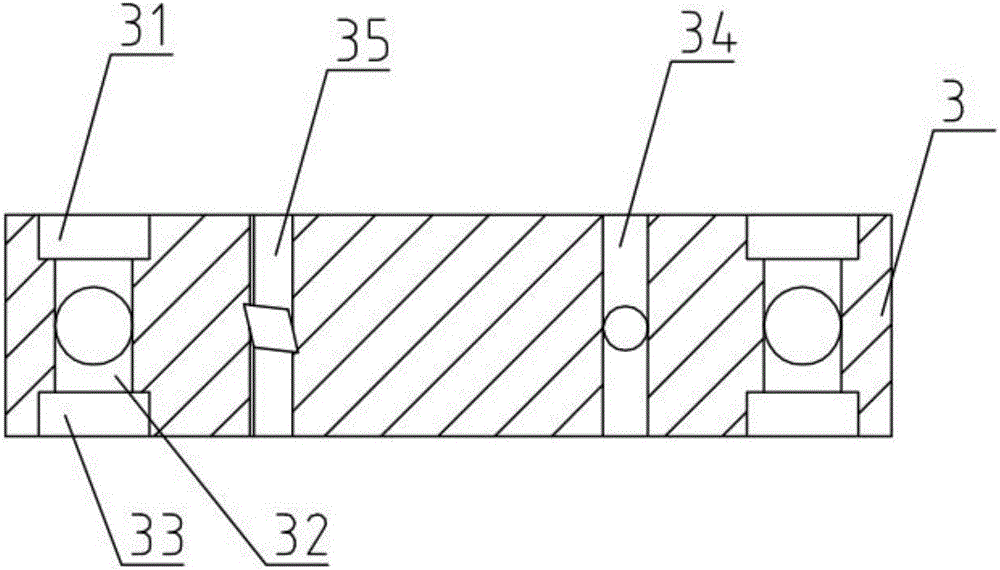
[0030] like figure 1 , figure 2 , image 3 and Figure 4 As shown, it is a combined blanking die of the present invention, which includes a die base 1 and a backing plate 2 installed on the die base 1 with several positioning threaded holes 21 at equal intervals on the plane, and also includes a base plate 2 arranged on the die base 1 Four rectangular parallelepiped modules 3 with a square cross-section on the upper plane of the backing plate 2, the four long edges of the module 3 are provided with cutting edges, and the modules 3 are arranged on any two mutually perpendicular planes along the direction of the four long edges. There are two countersunk head installation holes 32 which are mutually isolated and perpendicular to each other and symmetrica...


PUM


Abstract

The invention discloses a combined type blanking female die. The blanking female die comprises a die base and a base plate mounted on the upper plane of the die base and provided with a plurality of positioning threaded holes at equal intervals. The blanking female die further comprises four cuboid die blocks. Each die block is provided with vertically symmetric countersunk mounting holes, cylindrical positioning holes and rhombic positioning holes. A square cavity is defined by the four die blocks, the four die blocks are positioned through countersunk screws, cylindrical positioning pins and rhombic positioning pins, and the countersunk screws, the cylindrical positioning pins and the rhombic positioning pins are mounted in the positioning threaded holes in the base plate. A material returning plate and material returning rods are further arranged in the square cavity. Through position arrangement of the die blocks, the same set of die blocks can be conveniently combined into the square hole blanking female die in various dimensions, and the application range of the die is enlarged. Four edges of each die block in the length direction can be used as cutting edges, so that the service life of the die is prolonged to the greatest extent. The die blocks are spliced to form the female die, so that consumption of die materials is reduced, and the phenomenon of stress concentration at corners of the whole female die is overcome. Meanwhile, design and manufacturing of the female die are simplified.

Description

technical field [0001] The invention relates to a punching die, more specifically to a combined punching die and an assembly method thereof, belonging to the technical field of die manufacturing. Background technique [0002] Square hole making is widely used in thin plate processing, such as the load switch operation hole on the panel of the switch control box of household appliances, etc. At present, the production of conventional square holes in thin plates is formed by die punching. Usually, a set of molds is used for a square hole of one specification, and the concave and convex molds are usually integral, that is, the concave and convex molds are composed of one part. The corners of the die die are sharp corners. During the process of machining and heat treatment, stress concentration is likely to occur at the sharp corners, causing cracks at the corners and making the mold invalid. Therefore, the existing square-hole integral blanking dies can only be used in one-to-...

Claims


Application Information

Patent Timeline
Patent Type & Authority Applications(China)
IPC IPC(8): B21D28/14B21D37/20B26F1/44
CPCB21D28/14B21D37/205B26F1/44B26F2001/4445B26F2001/4463
Inventor 凌有临周云祥
Owner JIANGSU UNIV OF SCI & TECH
Why Eureka
Try Eureka