Plate punching die and punching method thereof

A plate and punching technology, applied in the field of stamping die, can solve the problems of complicated die replacement, poor punching accuracy, low punching efficiency, etc., and achieve the effects of easy replacement, less time and high processing efficiency.

Active Publication Date: 2016-09-07
JINSHEN NUMERICALLY Y CONTROLLED MOLDS
View PDF16 Cites 8 Cited by
  • Summary
  • Abstract
  • Description
  • Claims
  • Application Information

AI Technical Summary

Problems solved by technology

[0007] Aiming at the problems of cumbersome mold replacement, low punching efficiency and poor punching precision when the existing sheet is punched on a punching machine, the present invention provides a sheet punching die and a punching method thereof, which can quickly replace punches and The relative p

Method used


Image

  • Plate punching die and punching method thereof
  • Plate punching die and punching method thereof

Examples


Embodiment 1

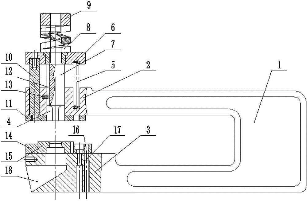
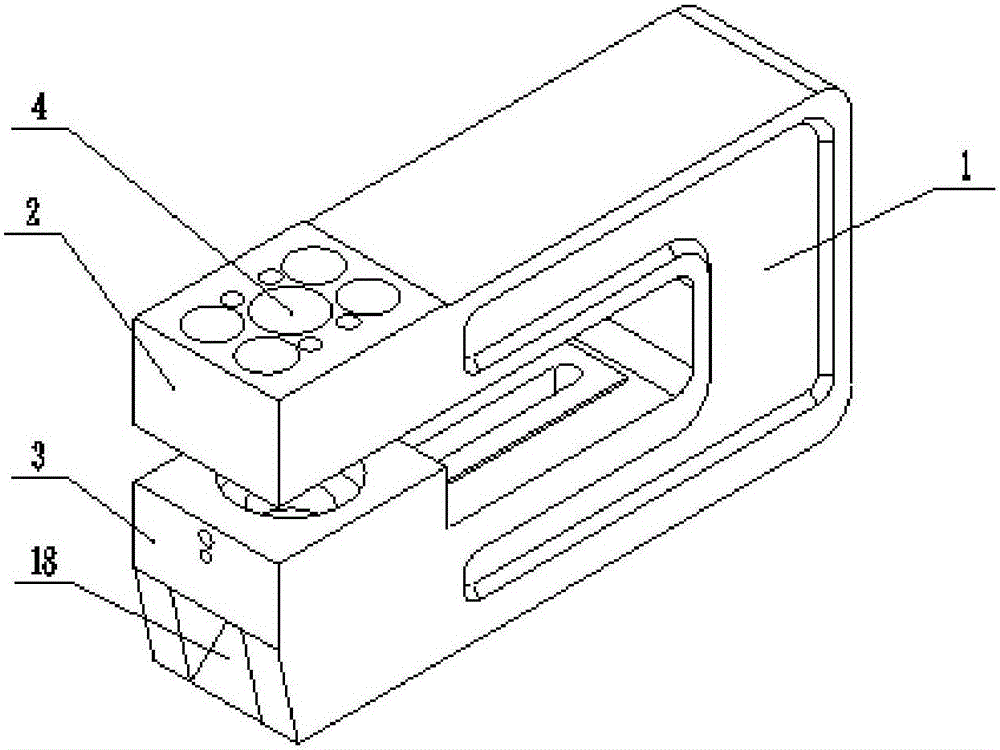
[0038] Such as figure 1 with figure 2 As shown, a sheet metal punching die of this embodiment includes a die base 1, a punch 7, a die 15, a contour screw 10, and a die fixing plate 14. Wherein, the mold base 1 has a "C"-shaped structure, and the two ends of the opening respectively have a punch support portion 2 and a die support portion 3; the punch support portion 2 is provided with a punch accommodating hole 4 , The punch 7 is arranged in the punch accommodating hole 4, the upper end of the punch 7 is threadedly connected with a hitting head 9; the punch 7 between the hitting head 9 and the punch support 2 is sleeved with a support plate 6 The discharging spring 8 is provided between the pallet 6 and the striking head 9, and the bracket spring 5 is provided between the pallet 6 and the punch support part 2. The elastic coefficient of the discharging spring 8 is greater than that of the bracket spring 5. coefficient. One end of the equal-height screw 10 is connected with t...

Embodiment 2

[0052] The basic structure of a plate punching die of this embodiment is the same as that of embodiment 1, except that the distance from the lower end surface of the punch 7 to the upper surface of the die 15 is A, then Among them: b is the value of sheet thickness in millimeters, the value range of b is 2-20mm, β and λ are constant coefficients, β=4.8-5.2, λ=37-41; specifically in this embodiment, Punching the plate with thickness b=10mm, and take β=5, λ=39, then A=15.7mm.

[0053] Use the above-mentioned plate punching die to punch a plate with a thickness of b=10mm and punch out a circular hole with a diameter of 20mm. The operation steps are as follows:

[0054] 1) Install the die set 1 on the worktable of the punch press, and select the corresponding punch 7 and die 15 according to the hole with a diameter of 20mm to be punched;

[0055] 2) Install the die 15 on the die support 3 through the die fixing plate 14; install the punch 7 into the punch accommodating hole 4 of the pun...

Embodiment 3

[0062] The basic structure of a plate punching die of this embodiment is the same as that of embodiment 1, except that the distance from the lower end surface of the punch 7 to the upper surface of the die 15 is A, then Among them: b is the value of sheet thickness in millimeters, the value range of b is 2-20mm, β and λ are constant coefficients, β=4.8-5.2, λ=37-41; specifically in this embodiment, Punching the plate with thickness b=20mm, and taking β=5.2, λ=37, then A=26.4mm.

[0063] Use the above-mentioned plate punching die to punch a plate with a thickness of b=20mm and punch out a circular hole with a diameter of 20mm. The operation steps are as follows:

[0064] 1) Install the die set 1 on the worktable of the punch press, and select the corresponding punch 7 and die 15 according to the hole with a diameter of 20mm to be punched;

[0065] 2) Install the die 15 on the die support 3 through the die fixing plate 14; install the punch 7 into the punch accommodating hole 4 of the...


PUM

PropertyMeasurementUnit
Thicknessaaaaaaaaaa
Thicknessaaaaaaaaaa
Thicknessaaaaaaaaaa

Abstract

The invention discloses a plate punching die and a punching method thereof, and belongs to the field of punching dies. The die comprises a die rack, a punch, a female die body, screws with the same height and a female die body fixing plate. The die rack is of a C-shaped structure, and the two ends of an opening of the die rack are provided with a punch supporting part and a female die body supporting part correspondingly. The punch supporting part is provided with a punch accommodating hole, the punch is arranged in the punch accommodating hole, and the upper end of the punch is connected with a blowing head. A supporting plate is arranged between the blowing head and the punch supporting part. A discharging spring is arranged between the supporting plate and the blowing head, and a support spring is arranged between the supporting plate and the punch supporting part. One ends of the screws with the same height are connected with the supporting plate, and the other ends of the screws with the same height penetrate through the punch supporting part to be connected with a discharging plate. The female die body is mounted on the female die body supporting part through the female die body fixing plate. The punching die is high in punching efficiency and precision and convenient to replace, has the advantages of being simple in structure, easy to operate, flexible in machining, low in cost and long in service life, and is capable of punching products in various specifications.

Description

Technical field [0001] The invention belongs to the field of stamping dies, and more specifically, relates to a plate punching die and a punching method thereof. Background technique [0002] The punch is a punch press. In national production, the stamping process has the advantages of saving materials and energy than traditional mechanical processing, high efficiency, low technical requirements for operators, and various mold applications that can make products that cannot be achieved by mechanical processing. Therefore, It has more and more uses. Stamping production is mainly for plates. Through molds, blanking, punching, forming, deep drawing, trimming, fine blanking, shaping, riveting and extrusion parts can be made, which are widely used in various fields. [0003] The punching machine can punch round holes, square holes, long round holes and various special-shaped holes on the plate through the punching die. At present, the punching die on the punch press is composed of an...

Claims


Application Information

Patent Timeline
IPC IPC(8): B21D28/34B21D28/26
CPCB21D28/26B21D28/34
Inventor 袁洋袁飞袁佐钿石静云
Owner JINSHEN NUMERICALLY Y CONTROLLED MOLDS
Why Eureka
Try Eureka