Al technical title is built by PatSnap Al team. It summarizes the technical point description of the patent document.
A cutting device and profile technology, applied in the field of machining, can solve the problems affecting the use of profiles, poor applicability, and large vibration of profiles, and achieve the effects of extending service life, strong applicability, and easy cutting.
Inactive Publication Date: 2017-09-22
JIANGSU HAI HENG BUILDING MATERIAL MACHINERY CO LTD
View PDF5 Cites 0 Cited by
Summary
Abstract
Description
Claims
Application Information
AI Technical Summary
This helps you quickly interpret patents by identifying the three key elements:
Problems solved by technology
Method used
Benefits of technology
Problems solved by technology
The above two methods are complex in structure, time-consuming and laborious to operate, and the poor fixing effect of the profile during the cutting process causes large vibration of the profile, which will cause uneven cutting surface and many burrs, which will affect the use of the profile, and these profile cutting devices are often only applicable Applicable to one type of profile, or only applicable to one size of profile, poor applicability
Method used
Image
Click on the blue label to locate the original text in one second.
Reading with bidirectional positioning of images and text.
Examples
Embodiment Construction
[0014] The present invention will be further described in detail below in conjunction with the accompanying drawings and examples. The following examples are explanations of the present invention and the present invention is not limited to the following examples.
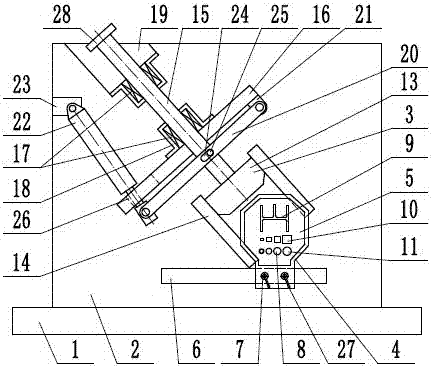
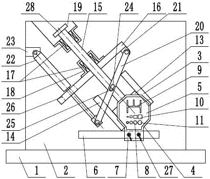
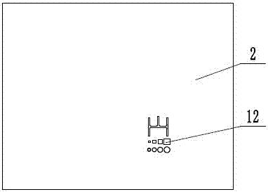
[0015] Such as figure 1 , figure 2 and image 3 As shown, a profile cutting device includes a base 1, a frame 2, a cutting mechanism 3, and a guiding mechanism 4. The guiding mechanism 4 realizes the guidance and support of the profile, and the cutting mechanism 3 realizes the rapid cutting of the profile. The frame 2 is fixed on the base 1, the guide mechanism 4 includes a guide plate 5, a support frame 6, and a locking screw 7, the support frame 6 is fixed on the frame 2, and the guide plate 5 is locked by locking The screw 7 is installed on the support frame 6, and the locking screw 7 is provided with a locking handle 27, which is beneficial for the operator to quickly realize the locking of the guide plate 5 ...
PUM
Abstract
The invention provides a section bar cut-off device, and belongs to the technical field of machining. The section bar cut-off device comprises a cut-off mechanism and a guide mechanism. A guide plate of the guide mechanism is installed on a bearing frame through locking screws. Section bar guide holes are formed in the guide plate. Guide grooves corresponding to the section bar guide holes in the guide plate are formed in a machine frame. A tool rest rod of the cut-off mechanism is arranged on slide guide sleeves in a slidable manner. A cut-off tool is installed at the lower end of the tool rest rod. Tool guide frames are arranged on the two sides of the cut-off tool. One end of a lever is hinged to a lever supporting lug. A U-shaped groove is formed in the middle end of the lever. A pin shaft is arranged on the tool rest rod and inserted in the U-shaped groove in the middle end of the lever. One end of a drive cylinder is hinged to a cylinder support, and the other end of the drive cylinder penetrates an anti-collision groove of a fixed support and is hinged to the other end of the lever. By means of the section bar cut-off device, section bars can be rapidly cut off, the surfaces of the section bars which are cut off are smooth, and the section bar cut-off device is suitable for the section bars of various shapes and types, reasonable in structure and high in applicability.
Description
technical field [0001] The invention relates to the technical field of mechanical processing, in particular to a profile cutting device. Background technique [0002] Section bar is an object with a certain geometric shape made of iron or steel and materials with certain strength and toughness (such as plastic, aluminum, glass fiber, etc.) through rolling, extrusion, casting and other processes. I-beams, channel steels, and angle steels are widely used in industrial buildings and metal structures, such as factories, bridges, ships, agricultural machinery and vehicle manufacturing, transmission towers, and transportation machinery. They are often used together. Flat steel is mainly used for bridges, house frames, fences, power transmission, ships, vehicles, etc. Round steel and square steel are used for various mechanical parts, agricultural machinery accessories, tools, etc. Profiles generally need to be cut to a certain length before use to adapt to subsequent processing ...
Claims
Application Information
Patent Timeline
Application Date:The date an application was filed.
Publication Date:The date a patent or application was officially published.
First Publication Date:The earliest publication date of a patent with the same application number.
Issue Date:Publication date of the patent grant document.
PCT Entry Date:The Entry date of PCT National Phase.
Estimated Expiry Date:The statutory expiry date of a patent right according to the Patent Law, and it is the longest term of protection that the patent right can achieve without the termination of the patent right due to other reasons(Term extension factor has been taken into account ).
Invalid Date:Actual expiry date is based on effective date or publication date of legal transaction data of invalid patent.
Patent Type & Authority Patents(China)
IPC IPC(8): B23D33/02B23D33/00B23Q5/34
CPCB23D33/00B23D33/02B23Q5/34
Inventor 王玉文陈欣刘立峰赵朝阳王云飞
Owner JIANGSU HAI HENG BUILDING MATERIAL MACHINERY CO LTD