Drilling pile casing guide device provided with calibration mechanisms and control method

A technology for calibrating mechanisms and guiding devices, which is applied in the direction of infrastructure engineering, construction, sheet pile walls, etc., can solve the problems of low efficiency, inability to guarantee the verticality of drilling casings, poor stability, etc., and achieve good safety and construction efficiency High and stable effect

Active Publication Date: 2016-09-07
ZHEJIANG JINZHU TRANSPORTATION CONSTR
View PDF7 Cites 8 Cited by
  • Summary
  • Abstract
  • Description
  • Claims
  • Application Information

AI Technical Summary

Problems solved by technology

[0005] The purpose of the present invention is to overcome the poor stability of the steel casing guide frame in the prior art, the inability to guarantee the verticality of the drilling casing, and the low efficiency, and to provide a method that can effectively control the verticality of the drilling casing , a drilling casing guide device with a calibration mechanism to improve construction efficiency

Method used


Image

  • Drilling pile casing guide device provided with calibration mechanisms and control method
  • Drilling pile casing guide device provided with calibration mechanisms and control method
  • Drilling pile casing guide device provided with calibration mechanisms and control method

Examples


Embodiment 1

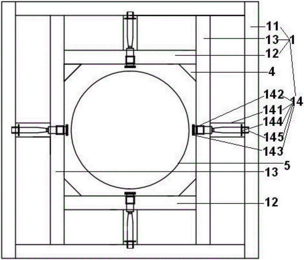
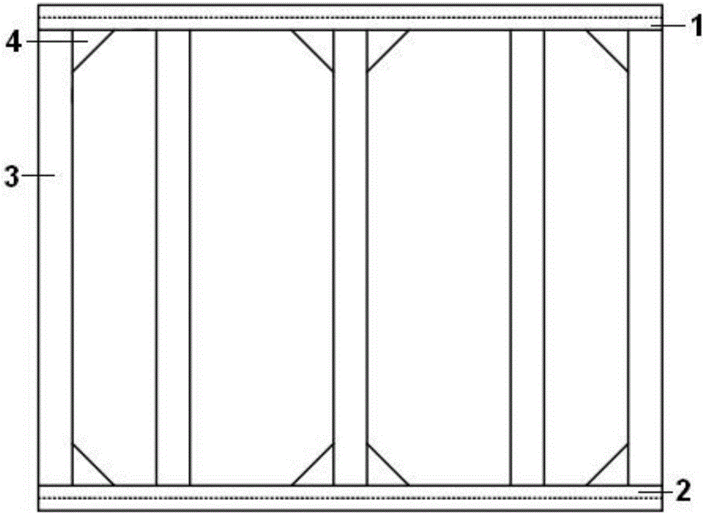
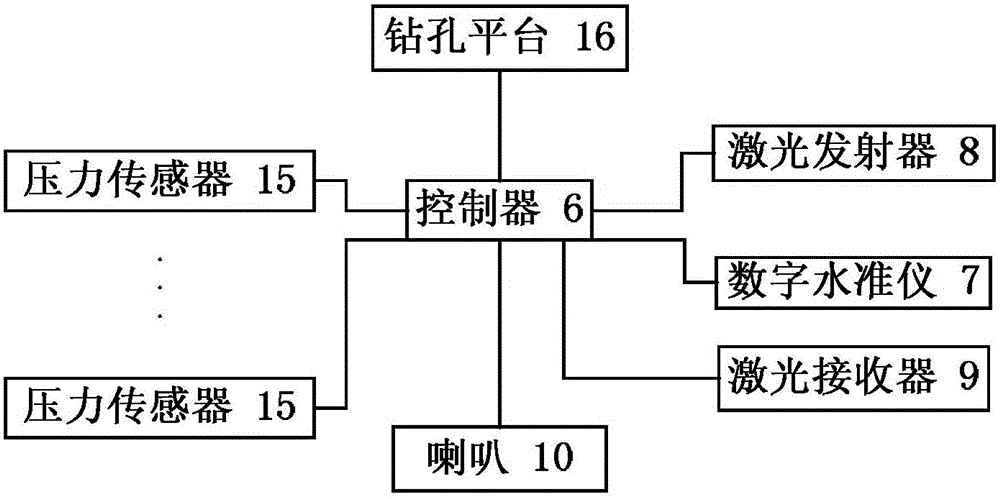
[0039] Such as figure 1 , figure 2 The illustrated embodiment is a drilling casing guide device provided with a calibration mechanism, including an upper bracket 1, a lower bracket 2, 12 support columns 3 arranged between the upper bracket and the lower bracket, a controller 6, and a digital Level 7, laser transmitter 8, laser receiver 9 and loudspeaker 10; The upper support includes a rectangular frame 11, two transverse bars 12 arranged in the rectangular frame, and two longitudinal bars 13 connected to the two ends of the two transverse bars respectively , the vertical calibration mechanism 14 that is located on the frame corresponding to the horizontal bar of each horizontal bar and the rectangular frame, and the 2 horizontal calibration mechanisms that are located on each vertical bar and the rectangular frame; as image 3As shown, the controller is electrically connected with the digital level, the laser transmitter, the laser receiver and the horn respectively, and th...

Embodiment 2

[0057] Embodiment 2 includes all methods and structural parts of embodiment 1, such as figure 1 As shown, each horizontal calibration mechanism and vertical calibration mechanism of Embodiment 2 all include a guide cylinder 141, a roller bracket 142 located at the front of the guide cylinder, a roller 143 located on the rotating shaft of the roller bracket, and a roller 143 located at the rear of the guide cylinder. The limiting plate 144 and the screw rod 145 located on the limiting plate; the roller bracket rear portion is provided with a sleeve, the front end of the screw is provided with an annular groove, and the annular edge located at the rear portion of the sleeve is embedded in the annular groove, and the annular The edge is slidingly connected with the annular groove, and the screw rod is threadedly connected with the limit plate; the drilling casing is provided with such as corresponding to each roller image 3 The pressure sensors 15 shown are each electrically con...


PUM


Abstract

The invention discloses a drilling pile casing guide device provided with calibration mechanisms and a control method. The device comprises an upper support, a lower support, a plurality of supporting columns arranged between the upper support and the lower support, a controller, a digital level, a laser emitter, a laser receiver and a horn. The upper support comprises a rectangular frame, two transverse rods arranged in the rectangular frame, two longitudinal rods connected with the two ends of the two transverse rods correspondingly, the longitudinal calibration mechanisms and the transverse calibration mechanisms, wherein the longitudinal calibration mechanisms are arranged on the transverse rods and borders, corresponding to the transverse rods, of the rectangular frame, and the transverse calibration mechanisms are arranged on the longitudinal rods and borders, corresponding to the longitudinal rods, of the rectangular frame. The controller is electrically connected with the digital level, the laser emitter, the laser receiver and the horn. The lower support is identical with the upper support in structure. The device and the method have the characteristics of being capable of effectively controlling the perpendicularity of drilling pile casings and high in construction efficiency.

Description

technical field [0001] The invention relates to the technical field of bored pile construction, in particular to a drilling casing guiding device provided with a calibration mechanism which can effectively control the verticality of the drilling casing and improve construction efficiency. Background technique [0002] Drilling casing insertion is an important process in the construction process of bored piles. At present, the mainstream drilling casing insertion is mainly controlled by two theodolites in two directions at a 90-degree right angle, and must be monitored throughout the insertion process. , very low efficacy. Even simple visual inspection and direct insertion can easily cause the verticality of the drilling casing to not meet the requirements, exceeding the 1% requirement of the specification, which may cause the drill bit to be stuck by the bottom of the casing. [0003] The lowering speed of the drilling casing is extremely slow, the efficiency is extremely l...

Claims


Application Information

Patent Timeline
Patent Type & Authority Applications(China)
IPC IPC(8): E02D13/04
CPCE02D13/04
Inventor 袁定辉刘向阳赵云强姚峰叶水标韩学明范远林宋松叶克定
Owner ZHEJIANG JINZHU TRANSPORTATION CONSTR
Why Eureka
Try Eureka