Novel packer based on ambient pressure

An environmental pressure and packer technology, applied in sealing/packing, wellbore/well components, earth-moving drilling, etc., can solve problems such as high cost, low maintenance cost, and the inability of driving equipment to be used for multiple cycles in the well , to achieve the effect of convenient operation, cost reduction, energy saving and accuracy

Active Publication Date: 2016-09-07
MUDANJIANG XINXIANG PETROLEUM MASCH CO LTD
View PDF12 Cites 7 Cited by
  • Summary
  • Abstract
  • Description
  • Claims
  • Application Information

AI Technical Summary

Problems solved by technology

[0003] The purpose of the present invention is to solve the problems of the existing mechanical packers, such as high cost, extra drive equipment and inability to be used repeatedly in downhole when setting and unsealing, to propose a method that adopts oil downhole environmental pressure As the drive source packer, the packer combines environmental pressure and hydraulic transmission. Its body adopts the form of double hydraulic cylinder drive and vacuum chamber oil return. It only needs to control the solenoid valve on the well to switch between setting and unsealing Action, and then control the movement direction of the hydraulic cylinder to complete the setting and unsealing of the packer, which simplifies the mechanical structure of the packer, realizes that it can drive a large load with a small power on the well and can be used repeatedly, making the equipment more efficient For energy saving and lower maintenance costs

Method used


Image

  • Novel packer based on ambient pressure
  • Novel packer based on ambient pressure

Examples


Embodiment Construction

[0022] The present invention will be further described in detail below in conjunction with the accompanying drawings and specific embodiments.

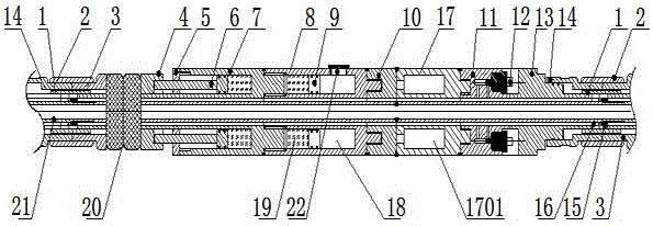
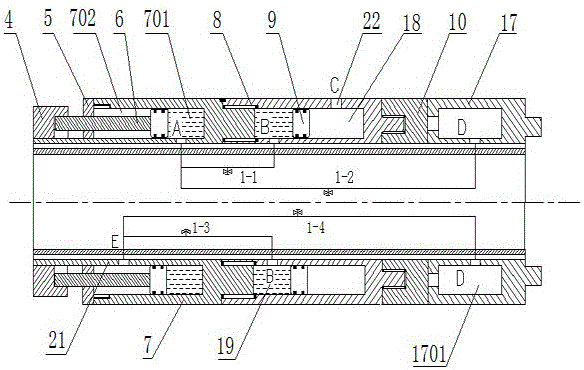
[0023] As shown in the figure, a new type of packer based on ambient pressure includes: a mandrel 21 fixedly arranged, the upper joint 14 and the lower joint 3 are sleeved on the mandrel 21, one end of the upper joint 14 and the end of the lower joint 3 One end is in close contact and its outer thread is sleeved with a connecting sleeve 2, the inner side of the upper joint 14 and the lower joint 3 are threaded with the mandrel 21 through the inner bushing 2, and the inner bushing plays a role of fastening to keep the cylinder coaxial Spend. The mandrel 21 is also provided with a rubber cartridge seat 4, and a rubber cartridge 20 is arranged between the lower joint 3 and the rubber cartridge seat 4. The rubber cartridge 20 is made of rubber material, which is easily deformed under pressure.

[0024] Also be provided with rear hydrauli...


PUM


Abstract

The invention discloses a novel packer based on the ambient pressure. A rear hydraulic cylinder, a front hydraulic cylinder and a vacuum oil tank are arranged on a spindle; a vacuum cavity is arranged in the vacuum oil tank; four oil circuits are arranged on the spindle; an oil return cavity of the front hydraulic cylinder is communicated with rodless cavities of the rear hydraulic cylinder through the oil circuits respectively; a rod cavity of the rear hydraulic cylinder is communicated with the vacuum oil tank; the oil return cavity of the front hydraulic cylinder is communicated with the rod cavity of the rear hydraulic cylinder; the rodless cavity of the rear hydraulic cylinder is communicated with the vacuum oil tank; solenoid valves are respectively arranged on the oil circuits; under the condition of starting setting, ambient pressure oil enters an oil inlet cavity of the front hydraulilc cylinder, pressure oil in the oil return cavity of the front hydraulic cylinder enters the rodless cavity of the rear hydraulic cylinder, oil liquid in the rod cavity of the rear hydraulic cylinder returns to the vacuum oil tank, a push rod compresses a rubber sleeve seat under the action of pressure so as to force a rubber sleeve to be stressed to deform, expand and compress a sleeve pipe, and the setting action is finished. The novel packer based on the ambient pressure provided by the invention adopts the ambient pressure under a petroleum well as a drive source, and no extra drive equipment is required, so that the cost is reduced, and the usage is more energy-saving.

Description

technical field [0001] The invention relates to a downhole oil layer protection packer, in particular to a new type of packer which adopts downhole oil well environment pressure as a driving source and combines the environment pressure with hydraulic transmission to realize isolation and delamination. Background technique [0002] Packer is a downhole tool used to control fluid production and protect casing by isolating production layers in oil production engineering. The annular space between the center pipe and the casing is sealed by the force deformation of the rubber tube, so as to achieve the purpose of downhole layered sealing. Due to the current lack of resources, oil production has begun to shift from shallow to deep. The environment of deep wells is harsh and mining is very difficult. During the oil production process, the requirements for setting and unsealing of packers are very strict. and performance requirements are very high. However, most of the existing p...

Claims


Application Information

Patent Timeline
Patent Type & Authority Applications(China)
IPC IPC(8): E21B33/126E21B33/127
CPCE21B33/126E21B33/127
Inventor 李阁强牛彦杰王帅郭冰菁李跃松赵书尚顾永升刘威张龙飞祖晓玲何社阳张福寿
Owner MUDANJIANG XINXIANG PETROLEUM MASCH CO LTD
Why Eureka
Try Eureka