

Discharging-assisted yield-increasing blowout liquid discharging natural gas recovery device and method
A recovery device and liquid drainage device technology, which is applied in the direction of earthwork drilling, production fluid, wellbore/well components, etc., can solve the problems of unfavorable natural gas wells, waste of resources, increased resistance of blowout, etc., to improve the effect of blowout, Avoid environmental hazards and meet the effect of spraying requirements
- Summary
- Abstract
- Description
- Claims
- Application Information
AI Technical Summary
Problems solved by technology
Method used
Image

Examples
Embodiment Construction
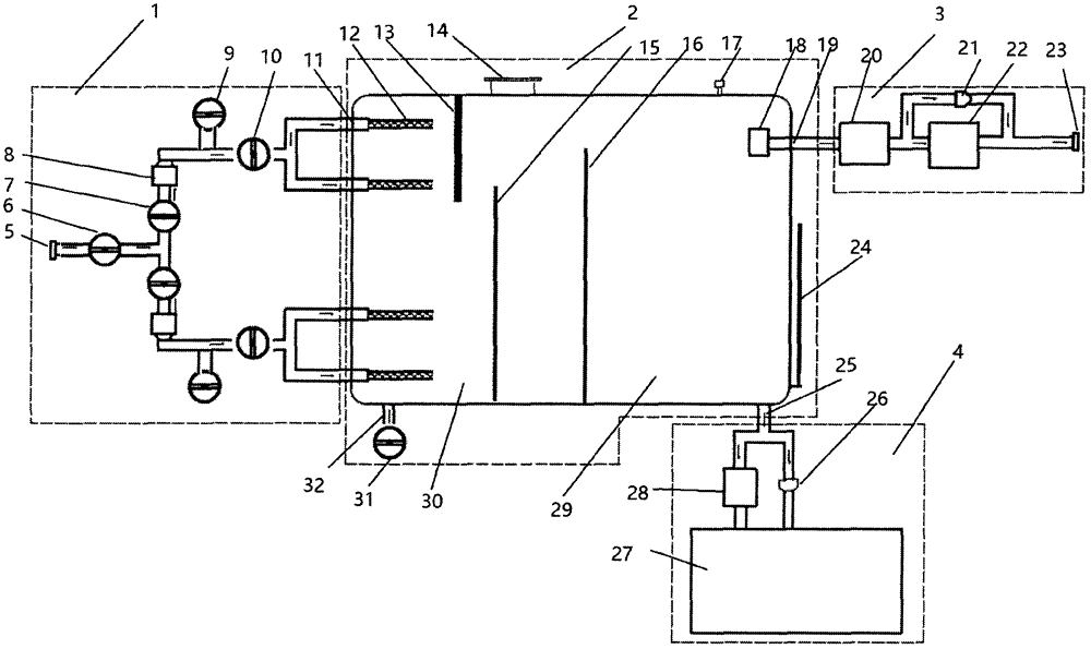
[0018] Such as figure 1 As shown, the recovery device and method for aiding drainage and increasing production, venting and discharging liquid natural gas are composed of a split flow venting device 1, a subsidence high-pressure recovery container 2, an external force aided drainage recovery device 3 and a liquid discharge device 4, and the valve 16 of the split venting device is connected to the The natural gas well blowout opening 5 is connected, and the pipeline behind the valve 1 is divided into two, and the liquid when the natural gas well blowout is blown is carried out a shunt. A valve II 7 is set on each pipeline after the primary diversion to control each pipeline individually. A nozzle cover 8 is connected behind the valve II to control the flowback liquid volume when replacing the nozzle. The outlet pipeline of the nozzle sleeve simultaneously It is connected with valve III 9 and valve IV 10. Valve III 9 is used for pressure relief when replacing the nozzle, and val...
PUM
 Abstract
Description
Claims
Application Information