A storage tank pressurized cryogenic liquid air energy storage system

A liquid air and energy storage system technology, applied in refrigeration and liquefaction, liquefaction, solidification, etc., can solve the problems of high cost and low operating efficiency, and achieve the effects of increased pressure, reduced cooling capacity, and reduced air circulation volume

Active Publication Date: 2017-11-07
GLOBAL ENERGY INTERCONNECTION RES INST CO LTD +3
View PDF6 Cites 0 Cited by
  • Summary
  • Abstract
  • Description
  • Claims
  • Application Information

AI Technical Summary

Problems solved by technology

[0003] Therefore, the technical problem to be solved by the present invention is to overcome the technical defects of low operating efficiency and high cost in the cryogenic liquefied air energy storage system in the prior art

Method used


Image

  • A storage tank pressurized cryogenic liquid air energy storage system

Examples


Embodiment 1

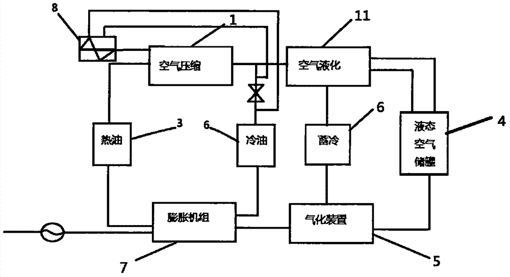
[0032] This embodiment provides a storage tank pressurized cryogenic liquefied air energy storage system, the following combination figure 1 The energy storage system of this embodiment is described in detail:

[0033] It includes: an air compressor unit 1, including several stages of air compressors to compress low-temperature and low-pressure air into high-temperature and high-pressure gaseous air;

[0034] The heat energy recovery device 3 collects the heat energy generated during the air compression process;

[0035] The liquid air storage tank 4 stores the high temperature and high pressure liquid air;

[0036] The gasification device 5 is used to gasify the high-temperature and high-pressure liquid air into high-temperature and high-pressure gaseous air, and receive the heat energy stored in the heat energy recovery device 3;

[0037] The cold energy recovery device 6 collects the cold energy generated during the gasification of liquid air into gaseous air, and release...


PUM


Abstract

The invention provides a storage tank pressurization type copious cooling liquid air energy storage system. A liquid air storage tank is connected with a pressurization device. The pressurization device is used for increasing the pressure in the liquid air storage tank and making the pressure in the liquid air storage tank be larger than the pressure of gas recycled by an air compressor unit. In this way, the saturation temperature of air liquefaction is increased while the pressure of the liquid air storage tank is improved, so that the needed refrigerating capacity is reduced, the flow of a refrigeration expander is reduced, the air circulation amount in a system is reduced, the power consumption of a circulating compressor is reduced, and the system efficiency is improved.

Description

technical field [0001] The invention relates to the technical field of cryogenic liquefied air energy storage, in particular to a storage tank pressurized cryogenic liquid air energy storage system. Background technique [0002] Cryogenic liquefied air energy storage technology refers to the use of electric energy for compressed air during the low load period of the grid, and the high-pressure sealing of the air in abandoned mines, subsidence subsea gas storage tanks, caves, expired oil and gas wells or newly built gas storage wells. The energy storage method releases compressed air during the peak period to drive the steam turbine to generate electricity. The liquid air energy storage system has the advantages of large energy storage capacity, long energy storage period, small footprint and does not depend on geographical conditions. During energy storage, the electric energy compresses, cools and liquefies the air, and at the same time stores the heat energy released durin...

Claims


Application Information

Patent Timeline
Patent Type & Authority Patents(China)
IPC IPC(8): F01K27/00F01K7/02F25J1/00
CPCF01K7/02F01K27/00F25J1/0012
Inventor 徐桂芝赵波杨岑玉王乐宋洁金翼邓占锋胡晓汤广福宋鹏翔李志远梁立晓
Owner GLOBAL ENERGY INTERCONNECTION RES INST CO LTD
Why Eureka
Try Eureka