Pressure reducing valve for high-pressure gas

A high-pressure gas, pressure reducing valve technology, applied in the direction of lift valve, valve details, safety valve, etc., can solve the problems of not being able to withstand shock and vibration, the performance parameters of the pressure reducing valve are no longer applicable, and the use pressure is high, to achieve impact resistance and resistance. Good vibration performance, large outlet flow and good stability

Inactive Publication Date: 2016-09-07
CHENGDU AEROSPACE FENGHUO PRECISION ELECTROMECHANICAL
View PDF8 Cites 5 Cited by
  • Summary
  • Abstract
  • Description
  • Claims
  • Application Information

AI Technical Summary

Problems solved by technology

[0005] C. Cannot withstand the impact of more than 8g and the vibration of more than 4g
[0006] In the field of new clean energy vehicles, in order to save energy and reduce the emission of vehicle pollutants, a new hydrogen fuel cell vehicle is proposed. At the same time, it is required that the valve products used in this field have a high pressure, and the mileage of a hydrogen fuel vehicle is comparable to that of an ordinary fuel vehicle. The mileage is quite equal, which makes the performance parameters of the original natural gas vehicle pressure reducing valve no longer applicable

Method used


Image

  • Pressure reducing valve for high-pressure gas
  • Pressure reducing valve for high-pressure gas
  • Pressure reducing valve for high-pressure gas

Examples


Embodiment Construction

[0020] The present invention will be further described below in conjunction with accompanying drawing:

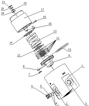
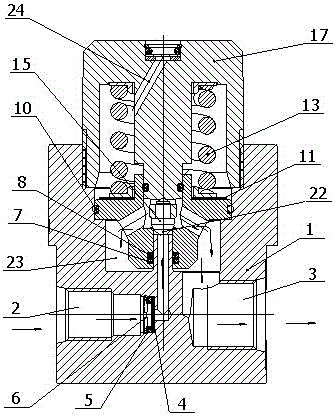
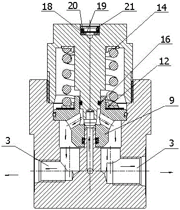
[0021] Such as figure 1 , figure 2 and image 3 As shown, the present invention includes a valve body 1 and a valve cover 17 arranged on the valve body 1, the valve body 1 is provided with an inner cavity 22, an outer cavity 23, an air inlet 2 and two air outlets 3, the air inlet 2 It communicates with the inner chamber 22, and the two air outlets 3 communicate with the outer chamber 23. A spring 13 is arranged in the valve cover 17, and a piston 9 is arranged in the outer chamber 23. One end of the spring 13 leans against the valve cover through the upper spring seat 14. 17 inner wall, the other end of the spring 13 leans against the piston 9 through the lower spring seat 12 and the multi-piece adjustment pad 11, the upper spring seat 14 is pressed against the inner wall of the valve cover 17 through the spring 13, the lower spring seat 12 and the multi-piece adjustment...


PUM


Abstract

The invention discloses a pressure reducing valve for high-pressure gas. The pressure reducing valve for the high-pressure gas comprises a valve body, and a cover which is arranged on the valve body, wherein the valve body is provided with an inner chamber, an outer chamber, a gas inlet and two gas outlets; the gas inlet communicates with the inner chamber, and the two gas outlets communicate with the outer chamber; a spring is arranged in the cover; a piston rod is arranged in the outer chamber; one end of the spring is propped to the inner wall of the cover through an upper spring seat, and the other end of the spring is propped to the piston through a lower spring seat and a plurality of adjusting cushions; the piston is pressed to an opening of the outer chamber through the spring; a first sealing ring is arranged between the piston and the inner wall of the valve body; the outer chamber is separated from the inner part of the cover through the piston and a first sealing ring; a ventilating hole is formed in the top part of the cover, and the inner part of the cover communicates with outside air through the ventilating hole; the piston is provided with an air flowing channel through which the outer chamber communicates with the inner chamber; a valve element is arranged in the air flowing channel; a gap is formed between the valve element and the air flowing channel. According to the pressure reducing valve for the high-pressure gas, all performance parameters of the pressure reducing valve are applicable to the pressure reduction of pipelines of a hydrogen fuel cell motor vehicle.

Description

technical field [0001] The invention relates to a high-pressure gas decompression valve, which is mainly used for decompression of hydrogen fuel cell pipelines in the newly developed new energy automobile industry. Background technique [0002] The gas tanks for CNG fuel vehicles in the prior art do not require very high pressure, temperature, vibration, impact, etc., the pressure is low, the various seals are well sealed, the joints can be welded, and various test environments can be changed without much change. test. The gas pressure reducing valve specifications for CNG energy vehicles are as follows: [0003] A. At present, the inlet of the pressure reducing valve for CNG fuel vehicles is generally below 25MPa, and the pressure reduction at the inlet and outlet is relatively small, generally 10-30; [0004] B. The operating temperature is mostly at room temperature -20~50°C; [0005] C. It cannot withstand the impact of more than 8g and the vibration of more than 4g. ...

Claims


Application Information

Patent Timeline
Patent Type & Authority Applications(China)
IPC IPC(8): F16K1/32F16K27/12F16K17/30
CPCF16K1/32F16K17/30F16K27/12
Inventor 林春荣胡国辉陈丽慧苟大利苟渝路刘惠明王照华苏光英
Owner CHENGDU AEROSPACE FENGHUO PRECISION ELECTROMECHANICAL
Why Eureka
Try Eureka