
Electric gate valve for controlling steam flow

A steam flow and flapper valve technology, which is applied in the direction of sliding valves, valve details, valve devices, etc., can solve the problems of remote automatic control of unfavorable steam flow, micro-leakage of high-pressure steam, etc., and achieve remote automatic control of steam flow, control Stable and reliable performance, convenient maintenance and repair

Inactive Publication Date: 2016-09-07
TONGLING DONGFANG MINING MASCH CO LTD
View PDF4 Cites 0 Cited by
  • Summary
  • Abstract
  • Description
  • Claims
  • Application Information

AI Technical Summary

Problems solved by technology

This control method is easy to cause the problem of micro-leakage of high-pressure steam, and it is not conducive to the remote automatic control of steam flow

Method used


Image

  • Electric gate valve for controlling steam flow

Examples


Embodiment Construction

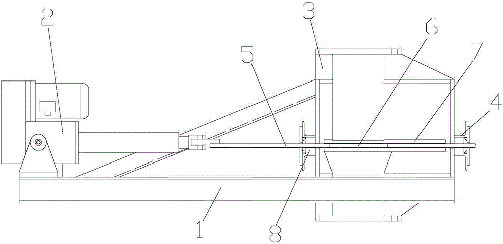
[0011] like figure 1 shown. The electric flapper valve for controlling steam flow includes a frame 1 made of channel steel, an electric push rod 2 is installed on the upper left end of the frame 1, and a box body 3 formed by welding steel plates is installed on the upper right end of the frame 1. 3 has a vertical chamber 31, the rod end of the electric push rod 2 on the frame 1 points to the box body 1 along the left and right directions, and the left and right side walls of the box body 1 are respectively provided with connecting pipes 4, and the left and right sides The connecting pipe 4 is located in the linear direction of the extension of the rod end of the electric push rod 2. Slideways are respectively arranged in the left side wall and the right side wall of the box body 3 along the linear direction of the extension of the rod end of the electric push rod 2, and the rod ends of the electric push rod 2 are connected. There is a horizontal board 5, and the board 5 is in...


PUM


Abstract

The invention discloses an electric gate valve for controlling the steam flow. The electric gate valve comprises a machine frame, an electric push rod is installed at the left end of the machine frame, a box body is arranged at the right end of the machine frame, a vertical chamber is formed inside the box body, the rod end of the electric push rod on the machine frame points to the box body, connecting pipes are arranged on the left side wall and the right side wall of the box body, sliding ways are formed in the left side wall and the right side wall of the box body, an insertion plate connected to the rod end of the electric push rod is inserted into the box body from the left side connecting pipe of the box body, sequentially penetrates through the sliding way in the left side wall and the sliding way in the right side wall and then extends out from the right side connecting pipe, and an open hole is formed in the insertion plate. The electric gate valve is easy to manufacture, low in cost, simple, practical and convenient to maintain and repair, can control high-pressure steam stably and reliably and overcomes the shortcomings of manually operating gates for controlling flow in the past.

Description

technical field [0001] The invention relates to the field of gate valves, in particular to an electric gate valve for controlling steam flow. Background technique [0002] In the chemical industry, pipelines are often used to transport steam, and the control of steam flow is generally realized by the staff manually operating the gate valve on the pipeline. This control method is easy to cause the problem of micro-leakage of high-pressure steam, and is not conducive to the remote automatic control of steam flow. Contents of the invention [0003] The object of the present invention is to provide an electric gate valve for controlling steam flow, so as to solve the problems in the prior art. [0004] In order to achieve the above object, the technical scheme adopted in the present invention is: [0005] The electric plug-in valve for controlling the steam flow includes a frame made of channel steel. Vertical chamber, the rod end of the electric push rod on the frame point...

Claims


Application Information

Patent Timeline
Patent Type & Authority Applications(China)
IPC IPC(8): F16K3/02F16K3/316F16K3/30F16K31/04
CPCF16K3/02F16K3/0227F16K3/316F16K31/04
Inventor 侯世祥
Owner TONGLING DONGFANG MINING MASCH CO LTD
Learn More