Light path heat dissipating combination system for spotlight

A combination system and heat dissipation system technology, applied in the field of spotlight road heat dissipation combination system, can solve the problems of affecting the illumination effect of LED spotlights, affecting the illumination effect of spotlights, and the beam angle becomes relatively large, so as to achieve improved light efficiency, low cost, The effect of short manufacturing process

Pending Publication Date: 2016-09-07
HUNAN MINGHE OPTO TECH
View PDF11 Cites 4 Cited by
  • Summary
  • Abstract
  • Description
  • Claims
  • Application Information

AI Technical Summary

Problems solved by technology

However, since the light source is packaged by multiple chips, or arranged on the same PCB board by multiple independent LEDs, there are square or circular arrangements, when the light source is located at the focal plane of the Fresnel lens, the Neel lens will project the images of neatly arranged LED chips, and the light spots will appear as multiple small squares instead of

Method used


Image

  • Light path heat dissipating combination system for spotlight
  • Light path heat dissipating combination system for spotlight
  • Light path heat dissipating combination system for spotlight

Examples


Embodiment 1

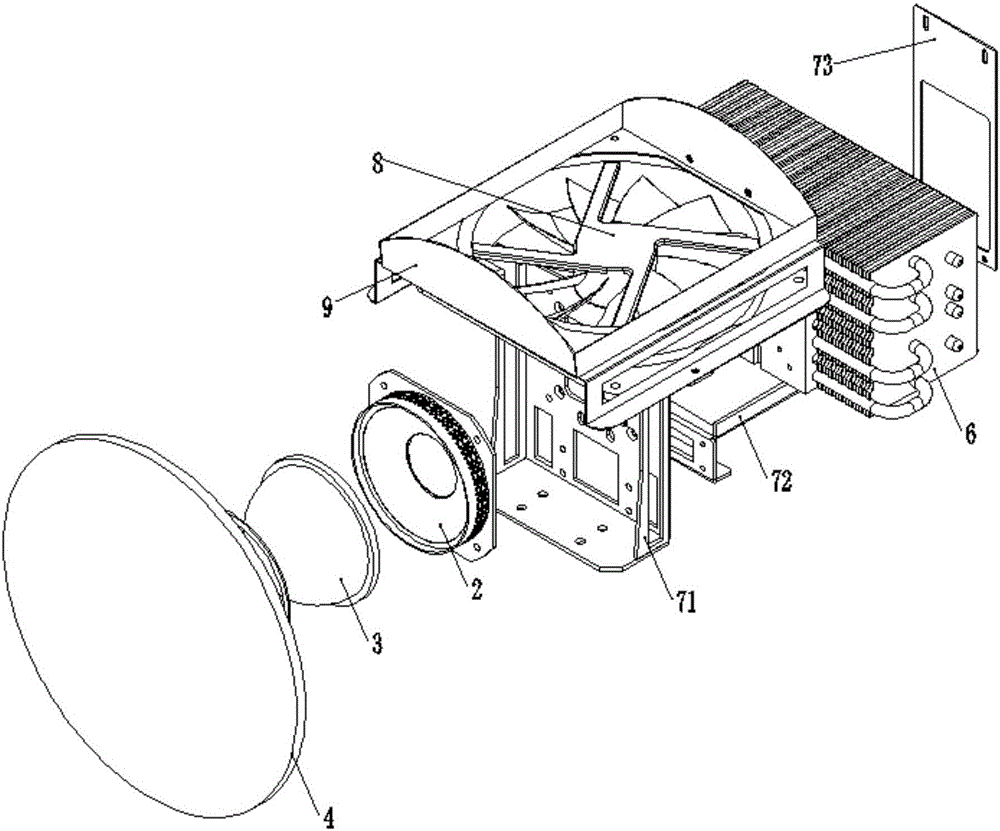
[0070] Such as Figure 1-7 As shown, this embodiment provides a spotlight path heat dissipation combined system, including an optical path system and a heat dissipation system, wherein:

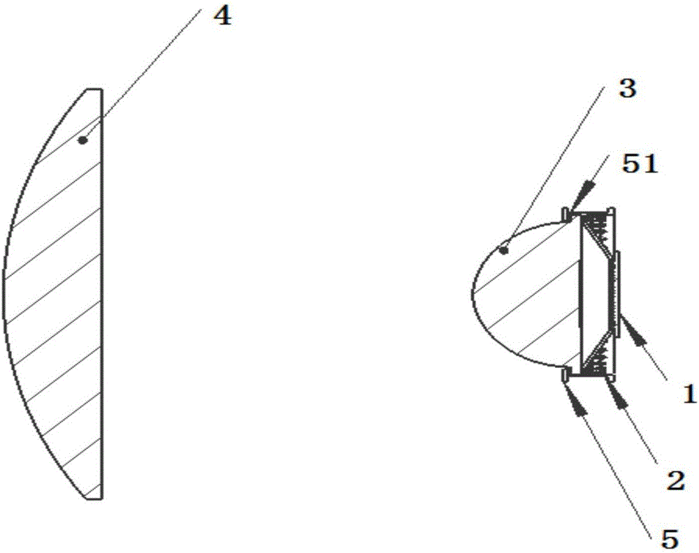
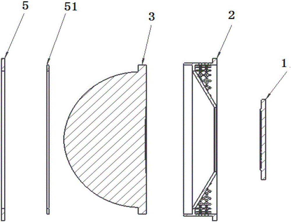
[0071] The optical path system includes: COB integrated light source 1, light receiver 2, aspheric mirror 3 (first-class lens), plano-convex mirror 4 (secondary lens);

[0072] Such as Figure 4 , 5 As shown, the light source light receiver 2 is a cylinder with openings at both ends, including a light inlet 201, a reflection part, and a light outlet 202. One end of the cylinder is the light outlet 202 of the light source receiver, and the end of the light outlet 202 is provided with a concave Enter the tapered surface 203 in the cylinder, the bottom of the tapered surface 203 forms an opening, which is the light inlet 201 of the light receiver, the end surface of the light inlet 201 is on the same level as the end surface of the other end of the cylinder, The tapered surface 203 is provide...


PUM


Abstract

The invention discloses a light path heat dissipating combination system for a spotlight. The light path heat dissipating combination system comprises a light path system and a heat dissipating system, wherein the light path system comprises a COB integrated light source, a light source light receiver, an aspherical mirror and a plano-convex lens; the light source light receiver is a cylinder body of which two ends are opened; a light emergent outlet is formed in one end of the cylinder body; a conical surface concaved into the cylinder body is arranged at the light emergent outlet end; an opening is formed in the bottom of the conical surface and is used as a light incident inlet; the end face of the light incident inlet and the end face of the other end of the cylinder body are positioned on the same horizontal plane; a vacuum coating layer is arranged on the conical surface; the vacuum coating layer and the conical surface jointly form a reflection part of the light source light receiver; the light incident inlet is greater than the light emergent outlet; the aspherical mirror is fixed at the light emergent outlet of the light source light receiver by an aspherical mirror pressing plate; an aspherical mirror silicone buffer washer is arranged between the aspherical mirror pressing plate and the light source light receiver; and center lines of the plano-convex lens, the aspherical mirror, the light source light receiver and the COB integrated light source are positioned on the same axis. The light path heat dissipating combination system disclosed by the invention has the characteristics of low cost, higher luminous efficacy, excellent heat dissipation potential and capability of prolonging the service life of the spotlight.

Description

technical field [0001] The invention relates to a spotlight, in particular to a heat dissipation combination system for spotlights and roads. Background technique [0002] Spotlight (spotlight) refers to a lamp that can use a condensing lens or a reflector to condense light. Spotlights cast a highly directional beam that produces bright highlights and sharp, dark shadows. [0003] At present, there are many kinds of spotlights on the market. The characteristics of spotlights are that the light projection distance is long, the range is obvious, the light direction is strong, its spot quality is high, the uniformity is good, and the edge of the illuminated object can be clear and sharp. , is a better local light transmission effect lamps. At present, threaded lens spotlights are the most, and threaded lens spotlights are Fresnel spotlights. Its optical system is composed of Fresnel lenses and spherical reflectors. Move back and forth along the optical axis to change the pro...

Claims


Application Information

Patent Timeline
IPC IPC(8): F21K9/20F21K9/60F21K9/69F21V5/04F21V19/00F21V29/83F21V17/12F21V29/51F21V29/76F21V29/67F21Y115/10
CPCF21V5/04F21V17/12F21V19/001F21V29/51F21V29/67F21V29/76F21V29/83
Inventor 杨勉傅高武傅高鹏
Owner HUNAN MINGHE OPTO TECH
Why Eureka
Try Eureka