Motorized spindle simulation working condition loading test device

A technology of loading test device and electric spindle, which is applied in the direction of measuring device, machine/structural component test, instrument, etc., can solve the problems of high cost, long maintenance and inspection cycle of electric spindle, lack of core technical data of electric spindle, etc., to achieve The effect of many measuring points and accurate response

Inactive Publication Date: 2016-09-07
YANCHENG INST OF TECH
View PDF7 Cites 3 Cited by
  • Summary
  • Abstract
  • Description
  • Claims
  • Application Information

AI Technical Summary

Problems solved by technology

[0003] At present, there is still a big gap between my country's electric spindle research, application and maintenance level and foreign countries. High-speed, high-precision electric spindles mainly rely on imports from Germany, Switzerland and other countries. The electric spindle lacks core technical information, as well as the lack of use and maintenance, resulting in the maintenance and testing of the electric spindle all relying on the electric spindle manufacturer. The maintenance and testing cycle of the electric spindle is long and the cost is high.

Method used


Image

  • Motorized spindle simulation working condition loading test device
  • Motorized spindle simulation working condition loading test device
  • Motorized spindle simulation working condition loading test device

Examples


Embodiment Construction

[0018] The present invention will be further described below in conjunction with the accompanying drawings.

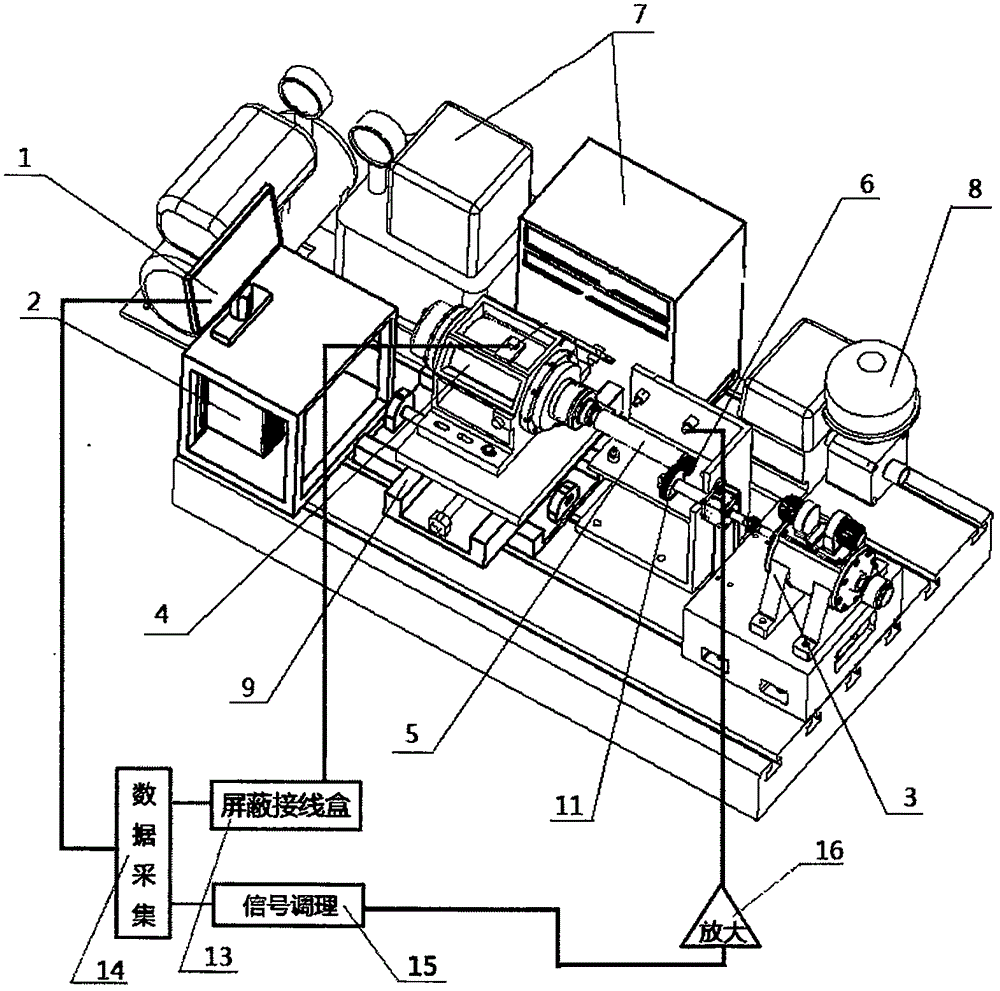
[0019] Such as figure 1 , figure 2 and image 3 As shown, a loading test device for an electric spindle simulating working conditions includes an industrial PC (1), a driving device (2) connected to the industrial PC (1), an electric spindle (4) connected to the driving device (2) and The loading driving mechanism (9), the test rod (5) is installed on the electric spindle (4), the loading driving mechanism (9) is installed under the electric spindle (4), the loading driving mechanism (9) is installed on the base of the test bench, cooled The water circulation device (7) and the oil-air lubrication device (8) are respectively connected with the electric spindle (4);

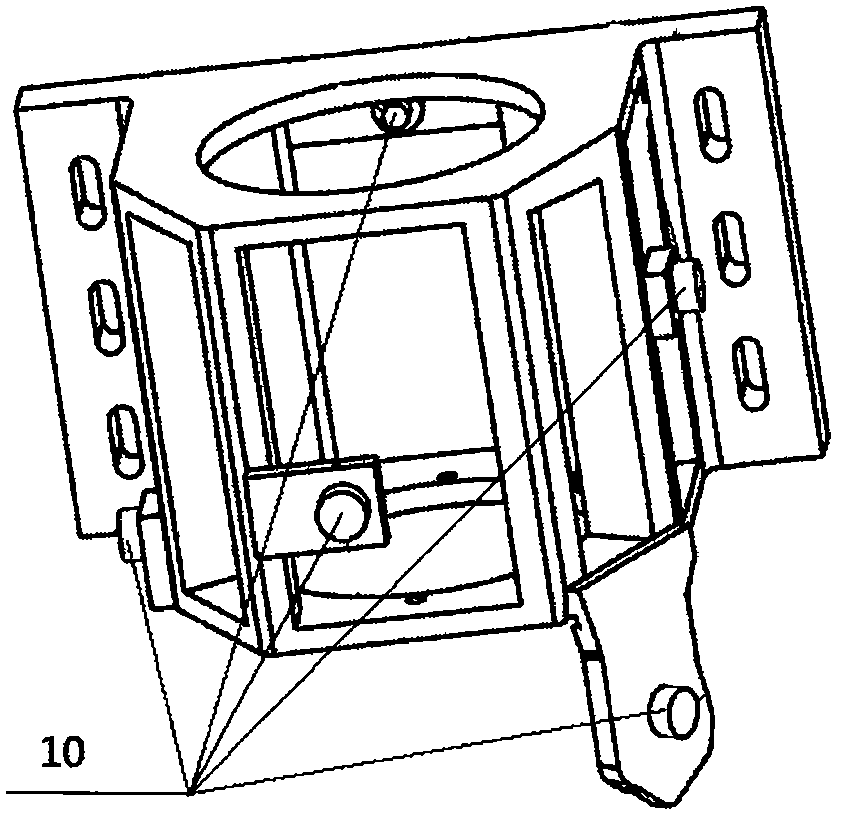
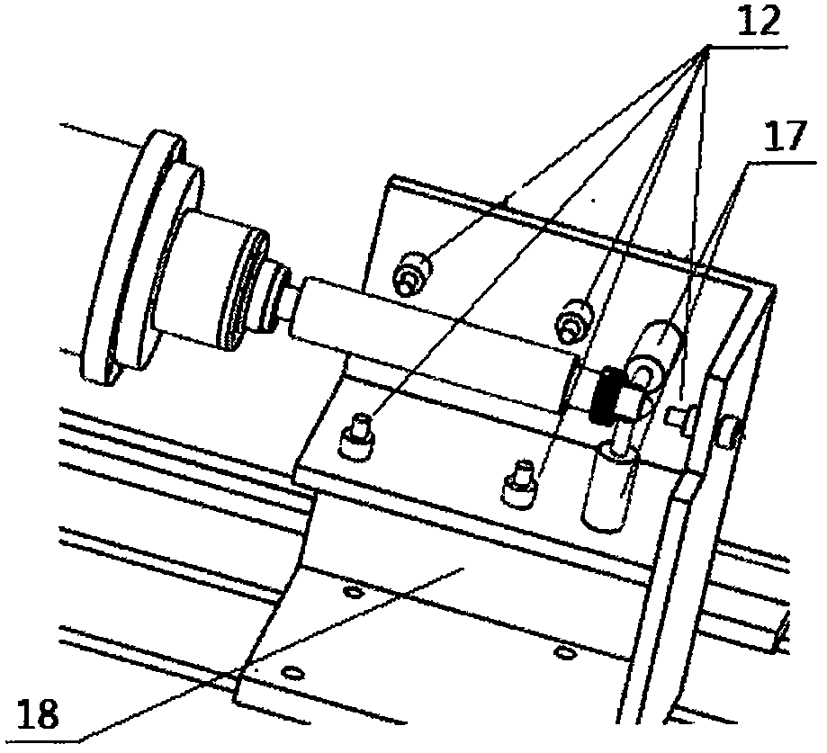
[0020] One side of the test rod (5) is provided with a detection sensor mounting frame (18), and the eddy current displacement sensor (12) is axially installed on the detection sensor mounting frame (1...


PUM


Abstract

The invention discloses a motorized spindle simulation working condition loading test device. The motorized spindle simulation working condition loading test device includes an industrial personal computer (PC), a driving device connected with the industrial PC, a motorized spindle connected with the driving device, and a loading driving mechanism; a test bar is arranged at the motorized spindle; the loading driving mechanism is installed below the motorized spindle; the loading driving mechanism is installed on a test bench base; and a cooling water circulation device and an oil-gas lubrication device are both connected with the motorized spindle. According to the motorized spindle simulation working condition loading test device of the invention, loading of a radial force, an axial force, a torque, vibration and heat cutting can be completed by means of simulation loading gears installed at an end portion of the test bar; the loading can be changed through replacing different types of gears and adjusting the modification coefficients of the meshing gears; and the loading driving mechanism is driven through a preset loading program to continuously move along the axial direction and the radial direction of the motorized spindle, so that the meshing condition of the loading gears can be automatically changed, and therefore, the simulation of automatic and continuous loading of an actual working condition can be completed, and thus, automation degree is high, a simulation condition is closer to an actual cutting working condition, and test data are more authentic.

Description

technical field [0001] The invention relates to a loading test device for simulating working conditions of an electric spindle, in particular to a device for carrying out a loading test of simulating working conditions for a high-speed electric spindle used in a numerically controlled machine tool before leaving the factory and after maintenance. Background technique [0002] Electric spindle is one of the core components of high-speed machining machine tools. It is also a high-performance spindle that integrates motors and rotating spindles in the field of CNC machine tools in recent years. It has compact structure, light weight, small inertia, small vibration, and low noise. Fast response and other advantages, with the development of CNC machining technology from traditional low-speed, low-feed, high-torque cutting to high-speed, high-feed cutting, electric spindles are widely used as high-speed spindle units for CNC machine tools. However, the electric spindle is a comple...

Claims


Application Information

Patent Timeline
IPC IPC(8): G01M99/00
CPCG01M99/00G01M99/007
Inventor 郑德星陈蔚芳王振宗
Owner YANCHENG INST OF TECH
Why Eureka
Try Eureka