
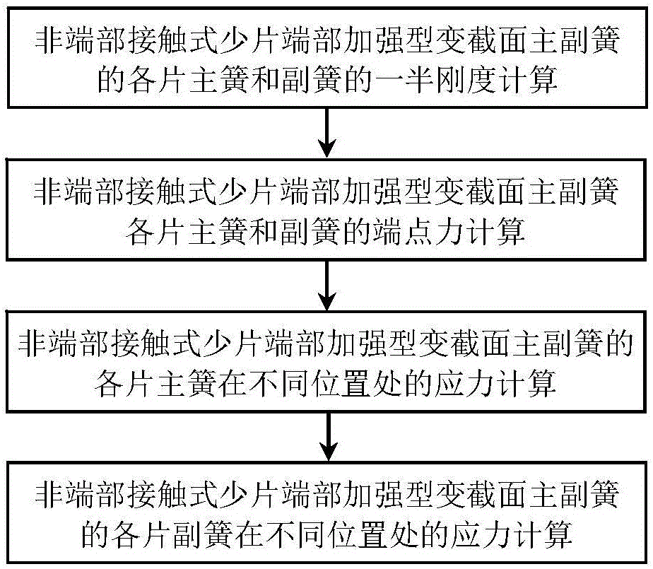
Calculation method for stress of each leaf of non-end-contact few-leaf end-enhanced main spring and sub-spring

A calculation method and contact technology, which is applied in calculation, special data processing applications, instruments, etc., can solve the problem of not being able to meet the requirements of non-end contact type, few-piece end-reinforced variable-section primary and secondary springs, and the inability to provide accurate stress analysis calculation formulas. And other issues

Inactive Publication Date: 2016-09-07
SHANDONG UNIV OF TECH
View PDF5 Cites 2 Cited by
  • Summary
  • Abstract
  • Description
  • Claims
  • Application Information

AI Technical Summary

Problems solved by technology

At present, at home and abroad, most of the main and auxiliary springs of the non-end contact type small-piece end-reinforced variable-section springs use finite element simulation software such as ANSYS to carry out the stress analysis of the few-piece variable-section main and auxiliary springs with a given structure and load through solid modeling. Numerical simulation, although this method can obtain relatively reliable stress simulation values, however, the finite element modeling and simulation analysis method can only perform numerical simulation verification on the stress of a small number of variable-section primary and secondary springs with a given structure and load, and cannot provide accurate Therefore, it cannot meet the requirements of CAD design and software development for the modern design of the main and auxiliary springs of the non-end contact type with few pieces of end reinforcement and variable cross-section.

Method used


Image

  • Calculation method for stress of each leaf of non-end-contact few-leaf end-enhanced main spring and sub-spring
  • Calculation method for stress of each leaf of non-end-contact few-leaf end-enhanced main spring and sub-spring
  • Calculation method for stress of each leaf of non-end-contact few-leaf end-enhanced main spring and sub-spring

Examples


Embodiment

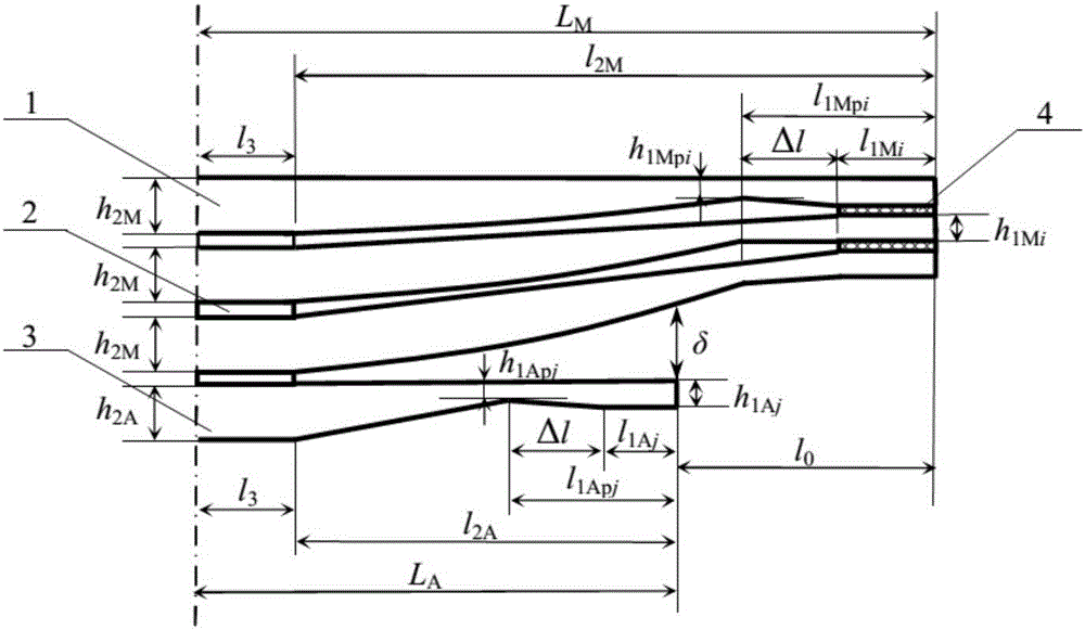
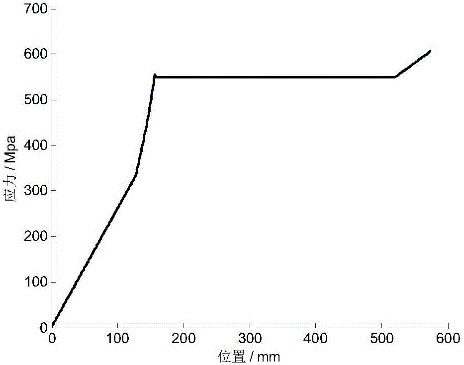
[0062] Example: The width b of a non-end contact type few-piece end-reinforced variable-section primary and secondary springs = 60 mm, half of the installation distance l 3 =55mm, length Δl of oblique line segment=30mm, elastic modulus E=200GPa. Half the length L of the main spring M =575mm,, the distance from the root of the main spring parabola segment to the end point of the main spring l 2M =L M -l 3 =520mm; the thickness h of the straight section at the root of each piece of main spring 2M =11mm, the number of main reeds m=2, where the end thickness h of the parabolic segment of the first main spring 1Mp1 =6mm, that is, the thickness ratio of the parabola segment β 1 =h 1Mp1 / h 2M =0.55, the distance l from the end of the parabola segment to the end point of the main spring 1Mp1 = l 2M beta1 2 =157.30mm, the thickness h of the straight section at the end 1M1 =7mm, that is, the thickness ratio of the oblique line segment γ M1 = h 1M1 / h 1Mp1 =1.17, the length...


PUM


Abstract

The present invention provides a calculation method for stress of each leaf of a non-end-contact few-leaf end-enhanced main spring and sub-spring, and belongs to the technical field of suspension leaf springs. According to the method provided by the present invention, stress of each leaf of main spring and sub-spring of a non-end-contact few-leaf end-enhanced main spring and sub-spring at different positions can be calculated according to a structure parameter of each leaf of the main spring and sub-spring, an elastic modulus, a load that makes the sub-spring function, and a load that the main spring bears. It can known by means of instances and ANSYS simulation verification that stress calculated values of each leaf of the main spring and sub-spring of the non-end-contact few-leaf end-enhanced main spring and sub-spring at the different positions can be accurately and reliably obtained according to the method, and by using the method, the design level, product quality, performance and reliability of a non-end-contact few-leaf end-enhanced tapered main-spring and sub-spring are improved, and smoothness and safety of vehicle driving are improved, the quality and cost of a suspension spring are reduced, and product design and experiment expenses are lowered, and product development and design speed is increased.

Description

technical field [0001] The invention relates to a vehicle suspension leaf spring, in particular to a method for calculating the stress of each leaf of a non-end contact type few-piece end-reinforced primary and secondary spring. Background technique [0002] Leaf springs with variable cross-sections are widely used in vehicle leaf spring suspension systems due to their advantages of light weight, small inter-sheet friction, and low noise. In order to meet the design requirements of processing technology, stress intensity, stiffness and lug thickness, in the actual engineering application process, the small-piece variable-section leaf spring is usually designed as a non-end contact type few-piece end-reinforced primary and secondary spring form. The stiffness of the main spring and the combined stiffness of the main and auxiliary springs should meet the requirements of the suspension characteristics, and the stress of each main spring and auxiliary spring at different positio...

Claims


Application Information

Patent Timeline
Patent Type & Authority Applications(China)
IPC IPC(8): G06F17/50
CPCG06F30/17G06F30/367
Inventor 周长城于曰伟赵雷雷邵杰汪晓邵明磊袁光明
Owner SHANDONG UNIV OF TECH
Learn More