Conveniently disassembled electrical connector having temperature resistance and pressure bearing

A technology for easy disassembly of electrical connectors. It is applied in the direction of connection, parts and circuits of connection devices. It can solve the problems of inconvenient maintenance and replacement of internal electronic instruments, poor strength of plastic materials, and jamming of container walls, etc., and achieves a simple structure. , reliable sealing and easy disassembly

Active Publication Date: 2016-09-07
SUZHOU HUAZHAN SPACE APPLIANCE
View PDF7 Cites 0 Cited by
  • Summary
  • Abstract
  • Description
  • Claims
  • Application Information

AI Technical Summary

Problems solved by technology

In order to ensure that the connector has good electrical performance, most of the existing electrical connectors with temperature-resistant and pressure-resistant structures are made of heat-resistant insulating materials. Creep deformation will occur, and it is easy to get stuck on the container wall after a long time of work. Due to the relatively poor strength of plastic materials and the effect of creep deformation, it is difficult to disassemble through the traditional tail thread method, which is difficult for the maintenance and replacement of internal electronic instruments. cause inconvenience

Method used


Image

  • Conveniently disassembled electrical connector having temperature resistance and pressure bearing
  • Conveniently disassembled electrical connector having temperature resistance and pressure bearing
  • Conveniently disassembled electrical connector having temperature resistance and pressure bearing

Examples


Embodiment Construction

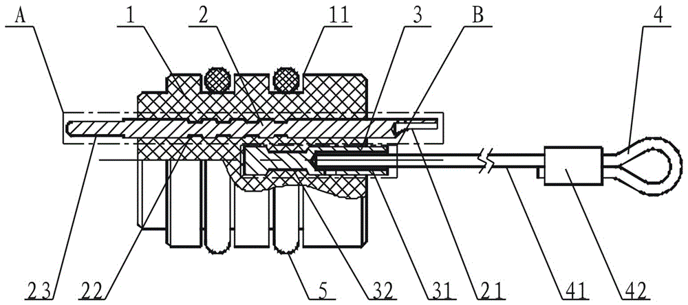
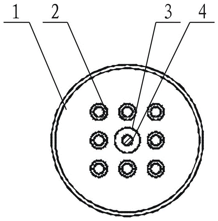
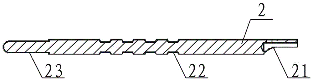
[0012] refer to figure 1 , figure 2 , image 3 , Figure 4 , the present invention includes an engineering plastic shell 1, a conductor contact piece 2, a crimping sleeve 3, a pull ring 4 and a sealing ring 5, the shell 1 is cylindrical, and the outer wall is radially provided with a sealing groove 11, and the conductor The contact piece 2 is a rod with a welding cup 21 at one end and a pin 23 at the other end. There are several grooves 22 on the body of the rod. The crimping sleeve 3 is a rod with a crimping hole 31 at one end. The body is provided with a ring groove 32, and the pull ring 4 is composed of a flexible metal rope 41 and a crimping piece 42;

[0013] One end of the flexible metal 41 on the pull ring 4 is set in the crimping hole 31 of the crimping sleeve 3 and crimped; the plurality of conductor contacts 2 are set in the casting mold along the axial direction of the housing 1, and pressed The connecting sleeve 3 is located on the axis of the housing 1 and is...


PUM


Abstract

The invention discloses a conveniently disassembled electrical connector having temperature resistance and pressure bearing. The electrical connector comprises a plastic housing, a conductor contact piece, a crimping sleeve, a pull ring and a sealing ring; the plastic housing is of a cylindrical structure which is provided with a sealing groove on an outer wall; the conductor contact piece is a rod piece; the pull ring and the crimping sleeve are combined together; the plastic housing wraps the conductor contact piece and the crimping sleeve in an injection moulding manner; and the sealing ring is arranged in the sealing groove of the plastic housing. According to the electrical connector disclosed by the invention, through the plastic housing and the sealing ring, a working environment where electrical signals at the two ends of the conductor contact piece are in a conducting state is isolated completely, and the conductor contact piece bears a pressure unidirectionally in the plastic housing; through moulding the crimping sleeve which is crimped with the pull ring in the plastic housing in an injection manner, the electrical connector can be taken out from a container by pulling the pull ring, thereby being convenient to disassemble the electrical connector; and the electrical connector has the advantages of convenience in disassembly, simple in structure, reliability in sealing, and good temperature resistance and pressure bearing properties.

Description

technical field [0001] The invention relates to the technical field of electrical connectors, which are used for the connection of instruments under high-temperature and high-pressure environments, in particular a detachable electrical connector with temperature resistance and pressure resistance. Background technique [0002] In the fields of oil drilling, well logging and seabed exploration, the operating point of the drilling equipment is often in the deep hole or deep on the seabed, and electronic equipment must be carried near the operating point to realize the transmission of downhole or seabed signals. The working environment of electronic equipment is quite harsh, especially the pressure or temperature environment is far from the ground. It is usually required to work at a temperature of 200°C and a pressure environment of 140MPa. There is a technology to place electronic equipment in a closed container, and install an electrical connector with a temperature-resistan...

Claims


Application Information

Patent Timeline
Patent Type & Authority Applications(China)
IPC IPC(8): H01R13/46H01R13/502H01R13/40H01R13/42
CPCH01R13/40H01R13/42H01R13/46H01R13/502
Inventor 栾东岳罗宁王敏兴
Owner SUZHOU HUAZHAN SPACE APPLIANCE
Why Eureka
Try Eureka