Permanent magnet linear oscillation motor with stator

A permanent magnet linear and oscillating motor technology, applied in electrical components, electromechanical devices, etc., can solve the problems of difficult heat dissipation, poor structural robustness, large mover inertia, etc., and achieve low cost, good working performance, and high power density. Effect

Active Publication Date: 2016-09-07
XIDIAN UNIV
View PDF3 Cites 6 Cited by
  • Summary
  • Abstract
  • Description
  • Claims
  • Application Information

AI Technical Summary

Problems solved by technology

Traditional moving-coil or moving-magnet linear oscillation motors have disadvantages such as large mover inertia, poor structural robustness, and difficult heat dissipation, which are not conducive to long-term frequent reciprocating motion of the motor.

Method used


Image

  • Permanent magnet linear oscillation motor with stator
  • Permanent magnet linear oscillation motor with stator
  • Permanent magnet linear oscillation motor with stator

Examples


Embodiment Construction

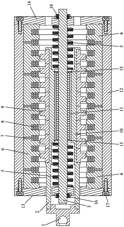
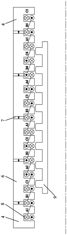
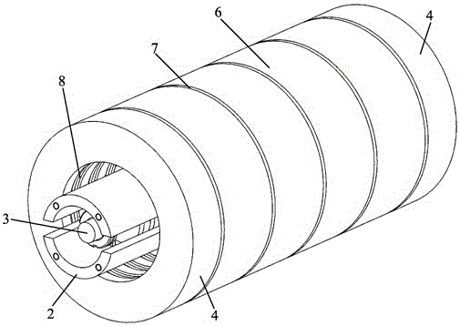
[0018] refer to figure 1 , image 3 and Figure 4 As shown, a stator permanent magnet linear oscillating motor of the present invention at least includes a connecting shaft end 1, an output bearing bush 2, a mover core shaft 3, a stator end ring gear 4, a resonant spring 5, a stator intermediate gear ring 6, a permanent magnet Steel ring 7, armature winding 8, mover gear ring 9, mover installation sleeve 10, linear sliding bearing 11, base sleeve 12; the mover mandrel 3 is axially arranged on the base sleeve In the center of cylinder 12, the mover mandrel 3 is fixed between the motor front end cover 13 and the motor rear end cover 14 through lock nuts 16; the motor front end cover 13 and the motor rear end cover 14 are respectively fixed on the machine body At both ends of the seat sleeve 12, there is a mover installation sleeve 10 in the middle of the mover core shaft 3; the mover gear ring 9 is sequentially nested on the outer surface of the mover installation sleeve 10 al...


PUM


Abstract

The invention relates to a permanent magnet linear oscillation motor with a stator. The permanent magnet linear oscillation motor is characterized by at least comprising a connecting shaft end, output bearing bushes, a rotor mandrel, a stator end part tooth ring, resonant springs, a stator middle tooth ring, permanent magnet steel rings, armature windings, rotor tooth rings, a rotor mounting sleeve, a linear sliding bearing and an engine base sleeve, wherein the rotor mandrel is arranged at the center of the engine base sleeve along the axial direction; the rotor mandrel is fixed between a front end cover of the motor and a rear end cover of the motor through locking nuts; the rotor mounting sleeve is arranged at the middle part of the rotor mandrel; the rotor tooth rings are sequentially nested into the excircle surface of the rotor mounting sleeve along the axial direction to form a linear motor secondary rotor; the linear sliding bearing is arranged at the inner side of the rotor mounting sleeve and is axially fixed by a snap spring; and a linear motor primary stator is fixed inside the engine base sleeve and outside the rotor tooth rings. The linear motor has more advantages as a high-thrust, high-power density and strong-robustness servo direct drive vibration source; and the working performance is better.

Description

technical field [0001] The invention belongs to the field of linear motion drive motors, in particular to a stator permanent magnet linear oscillating motor. Background technique [0002] The linear vibration motor is used to directly drive the load to do reciprocating linear motion, which saves the conversion device that converts rotary motion into reciprocating motion, improves the mechanical efficiency, and is widely used in high-frequency reciprocating motion fields such as linear compressors, vibrators, and electromagnetic pumps. Research application. Traditional moving-coil or moving-magnet structure linear oscillation motors have disadvantages such as large mover inertia, poor structural robustness, and difficult heat dissipation, which are not conducive to long-term frequent reciprocating motion of the motor. Contents of the invention [0003] In order to overcome the defects of the prior art, the purpose of the present invention is to provide a stator permanent m...

Claims


Application Information

Patent Timeline
Patent Type & Authority Applications(China)
IPC IPC(8): H02K33/18
CPCH02K33/18
Inventor 梁锦涛明正峰陈娟贺迪田博
Owner XIDIAN UNIV
Why Eureka
Try Eureka