
Spherical multi-degree-of-freedom piezoelectric actuator-based warhead deflection device

A technology of piezoelectric drive and deflection device, which is applied to piezoelectric effect/electrostrictive or magnetostrictive motors, generators/motors, electrical components, etc., and can solve complex structures, low control efficiency, and large warhead deflection angles. and other problems, to achieve the effect of simple and compact structure, simple control method and large output torque

Active Publication Date: 2016-09-07
NANJING UNIV OF SCI & TECH
View PDF6 Cites 3 Cited by
  • Summary
  • Abstract
  • Description
  • Claims
  • Application Information

AI Technical Summary

Problems solved by technology

This mechanism has good self-locking ability, but it can only achieve single-degree-of-freedom deflection. The two-dimensional ballistic correction is realized by continuously changing the direction of the bullet within one rotation cycle of the projectile. The control is complicated and the efficiency is low.
[0007] It can be seen from the above that the existing warhead deflection device has defects such as complex structure, large overall size, inconvenient control method, inability to provide a large warhead deflection angle, low control efficiency, and susceptibility to electromagnetic interference.
Therefore, there is an urgent need for a warhead deflection device with simple structure, convenient control, large output torque and no electromagnetic interference, but there is no relevant description in the prior art

Method used


Image

  • Spherical multi-degree-of-freedom piezoelectric actuator-based warhead deflection device
  • Spherical multi-degree-of-freedom piezoelectric actuator-based warhead deflection device
  • Spherical multi-degree-of-freedom piezoelectric actuator-based warhead deflection device

Examples


Embodiment

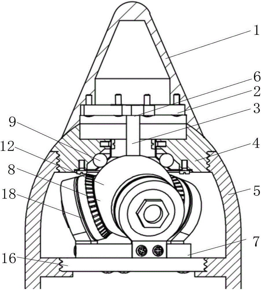
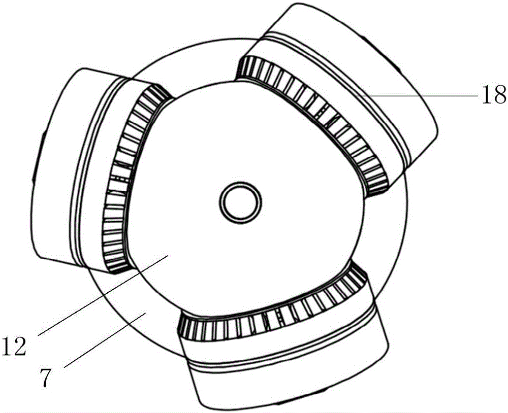
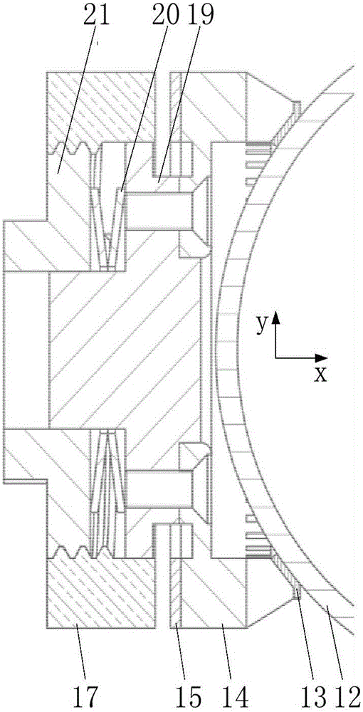
[0032] to combine figure 1 , a warhead deflection device based on a spherical multi-degree-of-freedom piezoelectric driver in this embodiment includes a deflectable warhead 1, a multifunctional helical column 4, a projectile body 5, a deflection connection mechanism 6, a spherical multi-degree-of-freedom piezoelectric driver 8, Roll mechanism 9 and threaded circular plate 16. The deflectable projectile 1 and the multifunctional helical column 4 are in spherical contact, and the multifunctional helical column 4 and the projectile body 5 are connected by threads. The spherical multi-degree-of-freedom piezoelectric driver 8 is located at the front end of the missile body 5, the spherical multi-degree-of-freedom piezoelectric driver 8 drives the deflectable projectile 1 to rotate through the deflection connection mechanism 6, and the rolling mechanism 9 is located at the multifunctional helical column 4 and the spherical multi-degree-of-freedom Between the piezoelectric drivers 8...


PUM


Abstract

The invention discloses a spherical multi-degree-of-freedom piezoelectric actuator-based warhead deflection device, which comprises a deflectable warhead, a multifunctional screw post, a projectile body, a deflection connecting mechanism, a spherical multi-degree-of-freedom piezoelectric actuator and a rolling mechanism, wherein the spherical multi-degree-of-freedom piezoelectric actuator comprises a ball rotor, a base and three stator mechanisms with a pre-tightening guide function; and under the action of adjusting nuts and disk springs, three stator elastic bodies and the ball rotor are in tight contact through friction gaskets. When certain voltage signals are supplied to three piezoelectric ceramic plates respectively, traveling waves can be stimulated on the surfaces of the stator elastic bodies; under the action of pre-tightening force, the ball rotor is driven to rotate around any axis which passes through the ball center through friction between a stator and the rotor; and the deflectable warhead is driven to deflect through the deflection connecting mechanism. The warhead deflection device disclosed by the invention is simple and compact in structure, high in output torque and high in response speed; electromagnetic interference is avoided; and multi-degree-of-freedom adjustment can be achieved.

Description

technical field [0001] The invention relates to a warhead deflecting device, in particular to a warhead deflecting device based on a spherical multi-degree-of-freedom piezoelectric driver. Background technique [0002] Bullet deflection ballistic correction means that during the flight of the projectile, the driver drives the warhead to deviate from the axis of the projectile. After the deflection, there is a pressure difference between the windward and leeward sides of the warhead, which produces the control force and control torque required to correct the ballistic. The flight attitude of the projectile to achieve the purpose of correcting the landing point. Compared with the widely used canard and pulse engine types, the warhead deflection type trajectory correction has better aerodynamic characteristics and higher control efficiency. At present, the existing warhead deflection mechanisms are mainly divided into piezoelectric ceramic rod type, magnetostrictive type, swas...

Claims


Application Information

Patent Timeline
Patent Type & Authority Applications(China)
IPC IPC(8): H02N2/10H02N2/12
CPCH02N2/108H02N2/123
Inventor 王炅杨建春陆飞
Owner NANJING UNIV OF SCI & TECH
Learn More