
Double-head pipe end forming machine

A technology of forming machine and double-headed pipe, applied in metal processing equipment, feeding device, positioning device, etc., can solve the problems of affecting the forming quality of pipe ends, reducing machining accuracy, affecting machining accuracy, etc., so as to improve the forming and processing quality, The effect of increasing the contact area and improving the machining accuracy

Active Publication Date: 2016-09-14
和和机械(张家港)有限公司
View PDF8 Cites 2 Cited by
  • Summary
  • Abstract
  • Description
  • Claims
  • Application Information

AI Technical Summary

Problems solved by technology

[0004] The double-head pipe end forming machine with the above-mentioned structure has the following disadvantages: 1. Due to the use of a single clamping frame, the clamping frame cannot well fix the pipe to be formed during the forming process, which causes the pipe to be formed to vibrate easily, thereby affecting The quality of pipe end forming, especially when forming long pipes with double-headed pipe ends, the forming accuracy is greatly reduced; 2. The forming oil cylinder, mold pipe seat and clamping frame are fixed and installed on the frame independently. There are cumulative errors in the installation process, which reduces the machining accuracy, and the forming cylinder will shake during the working process, which will also affect the machining accuracy

Method used


Image

  • Double-head pipe end forming machine
  • Double-head pipe end forming machine
  • Double-head pipe end forming machine

Examples


Embodiment Construction

[0016] The technical solutions of the present invention will be further described in detail below in conjunction with the accompanying drawings and preferred embodiments.

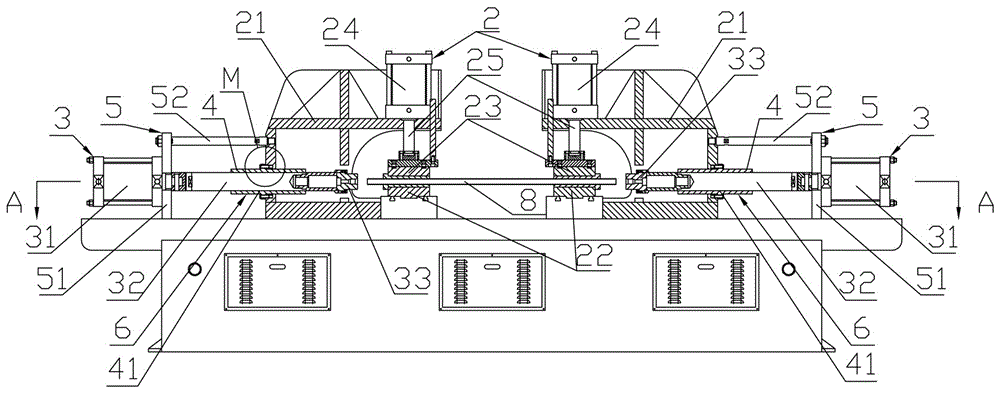
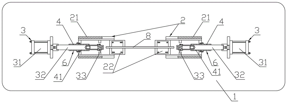
[0017] like figure 1 , figure 2 As shown, the double-head pipe end forming machine includes: a frame 1, a pair of clamping mechanisms and a pair of forming mechanisms symmetrically located on both sides of the pair of clamping mechanisms are arranged on the frame 1, and each clamping mechanism 2 includes The clamping frame 21 fixedly installed on the frame 1 is provided with a clamping gap for accommodating the pipe 8 to be formed in the clamping frame 21, and a lower clamping die 22 is arranged at the bottom of the clamping gap, and the upper part of the lower clamping die 22 is opposite Correspondingly, an upper clamping die 23 is installed movably, and a clamping oil cylinder 24 is also fixedly installed on the top of the clamping frame 21. The piston rod 25 of the clamping oil cylinder 24 passes downw...


PUM


Abstract

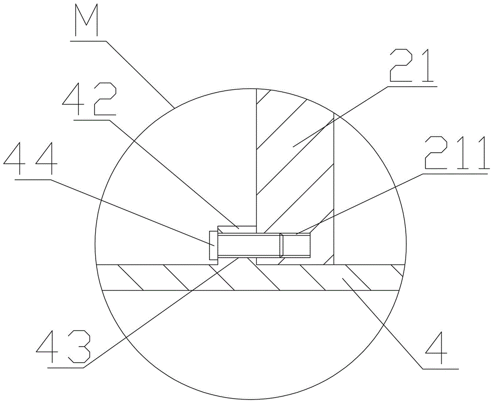
The present invention discloses a double-head pipe end forming machine which belongs to the field of pipe processing equipment. The forming machine comprises a rack, and the rack is provided with a pair of clamping mechanisms and a pair of forming mechanisms disposed symmetrically at two sides of the clamping mechanisms. Each clamping mechanism comprises a clamping support, the clamping support is internally provided with a clamping gap, a lower clamping die is disposed at the bottom part of the clamping gap, an upper clamping die is installed above the lower clamping die, a clamping oil cylinder is installed on the clamping support, a piston rod of the clamping oil cylinder penetrates through a top part of the clamping support and then is fixedly connected with the upper clamping die, and under a driving action of the clamping oil cylinder, the upper clamping die and the lower clamping die are clamped together or separated from each other. Each forming mechanism comprises a forming oil cylinder, a piston rod of the forming oil cylinder enters into the adjacent clamping support and stretches towards the clamping gap of the clamping support, and an end part of the piston rod of the forming oil cylinder is provided with a forming die. Both of the two clamping supports are provided with guiding mechanisms, and the piston rods of the forming oil cylinders enter into the clamping supports through the guiding mechanisms. The double-head pipe end forming machine provided by the present invention has the advantages of high machining precision.

Description

technical field [0001] The invention relates to the field of pipe material processing equipment, in particular to a double-head pipe end forming equipment. Background technique [0002] The double-head pipe end forming machine is a kind of equipment that can simultaneously form and process the two ends of the pipe workpiece. It is suitable for forming and processing various shapes of the joints of pipes, automobile oil pipes, air pipes, water pipes, and air-conditioning pipes. A kind of double-head pipe end forming machine commonly used in the industry at present, its structure comprises: frame, is provided with clamping mechanism and a pair of forming mechanism that is symmetrically positioned at the two sides of this clamping mechanism on the frame, and described clamping mechanism Including the clamping frame fixedly installed on the frame, the clamping frame is provided with a clamping notch for accommodating the pipe to be formed, the bottom of the clamping notch is fix...

Claims


Application Information

Patent Timeline
IPC IPC(8): B21D19/00B21D43/00
CPCB21D19/00B21D43/003
Inventor 黄俊杰
Owner 和和机械(张家港)有限公司
Learn More