Float type oil level detection device
A technology of oil level detection and float type, which is applied in the directions of lubrication indicator devices and lubrication parts, etc., which can solve the problems of rising costs and increasing the number of parts
- Summary
- Abstract
- Description
- Claims
- Application Information
AI Technical Summary
Problems solved by technology
Method used
Image


Examples
Embodiment 1
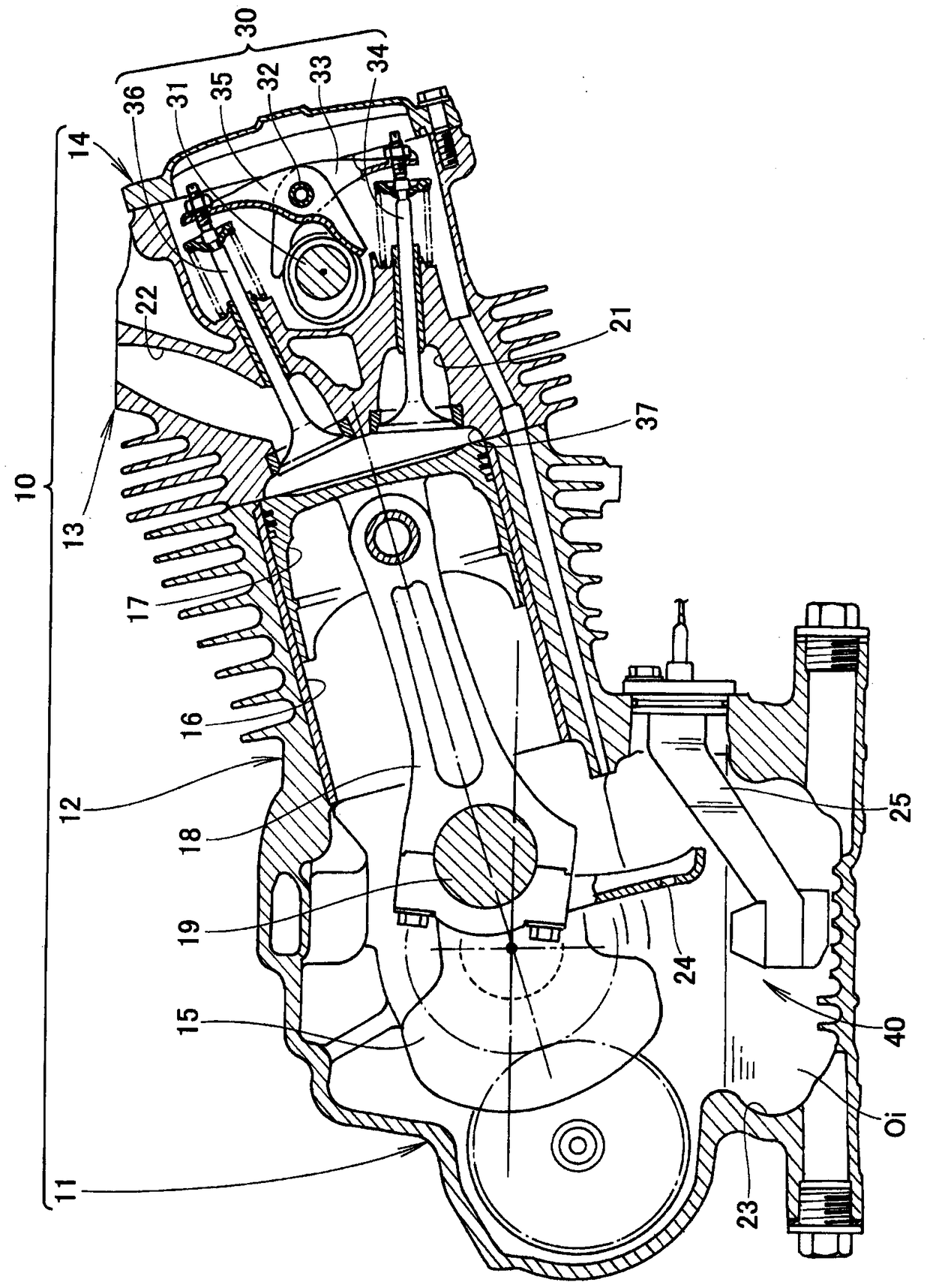
[0043] refer to figure 1 . figure 1 It is a sectional view of the engine 10 viewed from the direction in which the crankshaft 15 extends. The engine 10 is an inclined-cylinder type OHC air-cooled single-cylinder internal combustion engine in which the cylinder 16 is inclined with respect to the crankshaft 15 .
[0044] The engine 10 has: a crankcase 11; a cylinder block 12 integrally formed with the crankcase 11; a cylinder head 13 provided on an end of the cylinder block 12;
[0045] A crankshaft 15 is rotatably accommodated inside the crankcase 11 . A cylinder 16 is formed inside the cylinder block 12 , and a piston 17 reciprocating in the cylinder 16 is disposed. Piston 17 is connected to crankshaft 15 via connecting rod 18 and crankpin 19 .
[0046]An intake port 21 and an exhaust port 22 are formed inside the cylinder head 13 , and a valve drive mechanism 30 is also provided. The valve driving mechanism 30 is composed of a camshaft 31 , a swing shaft 32 , an intake v...
Embodiment 2
[0073] Next, Embodiment 2 of the present invention will be described. Embodiment 2 differs from Embodiment 1 in the shape of the inclined portion in the housing 50 and the float 60 . The other structures are the same as the oil level detection device 40 of the first embodiment, and the reference numerals are used below and the description is omitted.
[0074] refer to Figure 5 and Figure 6 (b). The top portion 70A of the housing 50A has a circular shape covering the upper end of the cylindrical portion 52 . Inside the casing 50A, a tapered shaft portion 73 whose diameter gradually decreases from the top portion 70A to the bottom portion 51 is provided. The through hole 63 penetrated by the tapered shaft portion 73 is formed in the float 60A, and the through hole 63 has a shape along the tapered shaft portion 73 .
[0075] Hereinafter, the action and effect of the present invention when the engine is dumped will be described in comparison with the prior art.
[0076] re...
Embodiment 3
[0086] refer to Figure 7 . The upper surface of the case 50B is constituted by a case-side hemispherical portion 70B having a substantially hemispherical shape and having a passage hole 72a at the end for allowing the oil Oi to enter and exit. The upper portion of the float 60B includes a float-side hemispherical portion 62B inclined so as to be movable along the case-side hemispherical portion 70B.
[0087] The predetermined effects of the present invention can also be obtained by using the oil level detection device 40B. Furthermore, the oil level detection device 40B can also obtain the following predetermined effects.
[0088] With the casing side truncated cone portion 71 of Embodiment 1 (refer to Figure 4 The case side hemispherical portion 70B bulges outward from the case 50B based on the inclined line L of (b)), so the float side hemispherical portion 62B is less likely to contact the case side hemispherical portion 70B. Therefore, when the engine 10 falls over, ...
PUM
 Abstract
Description
Claims
Application Information
 - R&D
- Intellectual Property
- Life Sciences
- Materials
- Tech Scout
- Unparalleled Data Quality
- Higher Quality Content
- 60% Fewer Hallucinations
Browse by: Latest US Patents, China's latest patents, Technical Efficacy Thesaurus, Application Domain, Technology Topic, Popular Technical Reports.
© 2025 PatSnap. All rights reserved.Legal|Privacy policy|Modern Slavery Act Transparency Statement|Sitemap|About US| Contact US: help@patsnap.com