
Ventilation and heat-dissipation structure of electric vehicle in-wheel motor

A hub motor and electric vehicle technology, applied to electric vehicles, motors, electric components, etc., can solve the problem that the air-cooled heat dissipation structure cannot meet the sealing requirements, and achieve good forced ventilation heat dissipation effect, taking into account compactness and manufacturing costs Economical and safe

Active Publication Date: 2016-09-14
ZHEJIANG ZHAOFENG MECHANICAL & ELECTRONICS CO LTD +1
View PDF4 Cites 2 Cited by
  • Summary
  • Abstract
  • Description
  • Claims
  • Application Information

AI Technical Summary

Problems solved by technology

On the other hand, considering that the vehicle may encounter water, rain and snow during driving, the in-wheel motor requires good sealing to prevent water from penetrating into the motor and damaging the winding insulation, causing electrical short circuit and chemical corrosion. However, the current wind The cooling and heat dissipation structure is still unable to solve the sealing requirements, and the above two requirements are contradictory, which has been perplexing those skilled in the art

Method used


Image

  • Ventilation and heat-dissipation structure of electric vehicle in-wheel motor
  • Ventilation and heat-dissipation structure of electric vehicle in-wheel motor

Examples


Embodiment Construction

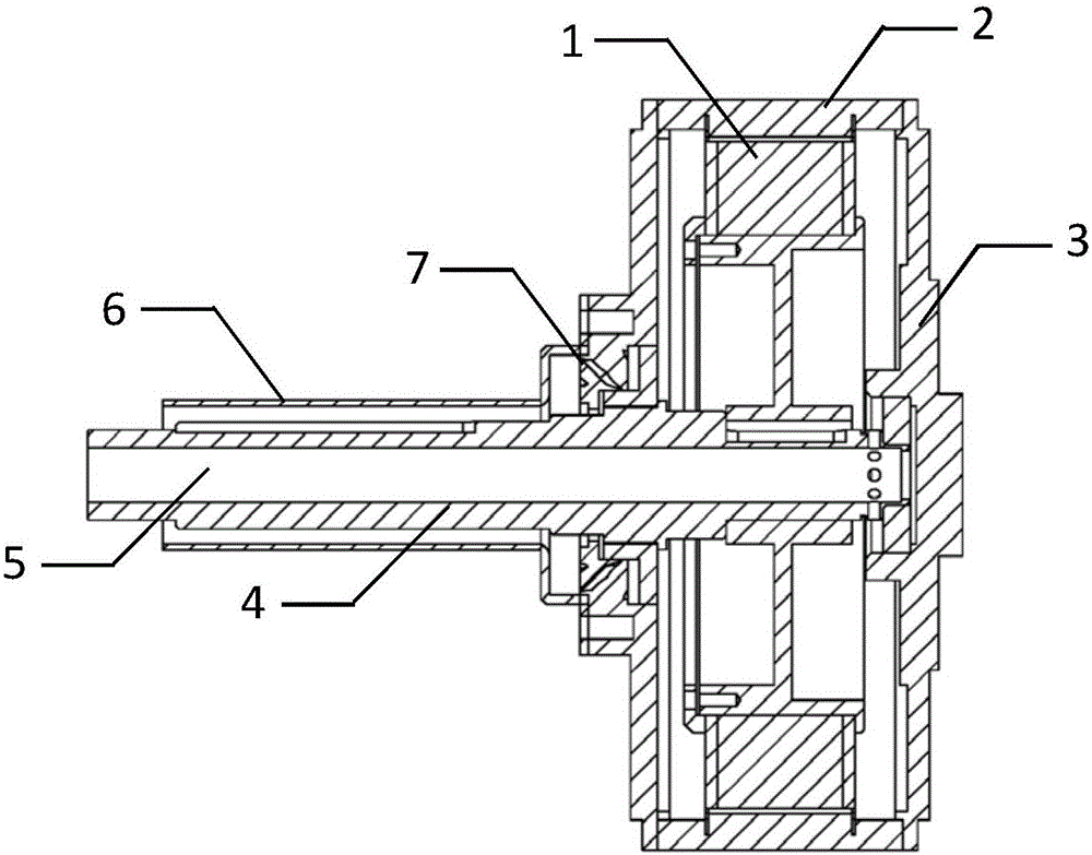
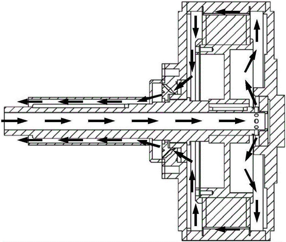
[0013] Such as figure 1 and figure 2 As shown, a waterproof and air-cooled heat dissipation structure of an electric vehicle hub motor includes an outer rotor 2 and an inner stator 1. The inner stator 1 is formed by stacking silicon steel sheets, and three-phase windings are embedded in the stator slots. The outer rotor 2 is arranged on the outer circumference side of the inner stator 1, and the inner side of the outer rotor 2 is uniformly embedded with permanent magnets. The inner stator 1 is installed on the motor shaft 4, and hub motor end covers 3 are arranged on both axial sides of the hub motor, including a left hub motor end cover and a right hub motor end cover, and the hub motor end cover 3 and The outer rotor 2 is fixed, a first bearing is provided between the motor shaft 4 and the end cover of the left hub motor, a second bearing is provided between the motor shaft and the end cover of the right hub motor, and the other end of the motor shaft is connected to the v...


PUM


Abstract

The invention discloses a ventilation and heat-dissipation structure of an electric vehicle in-wheel motor. In-wheel motor end covers are arranged at the left side and the right side of the in-wheel motor; a first bearing is arranged between a motor shaft and the in-wheel motor end cover at the left side; seal structures are arranged between the in-wheel motor end covers and the outer rotor and between the in-wheel motor end covers and the motor shaft; the motor shaft is provided with inner and outer two-layer concentric circle air ducts; the inner-layer air duct is an air inlet channel; the outer-layer air duct is an air outlet channel; one end of each of the air inlet channel and the air outlet channel communicate with an inner cavity of the in-wheel motor; and the other ends of the air inlet channel and the air outlet channel are connected with an air inlet and an air outlet respectively. By the ventilation and heat-dissipation structure of the electric vehicle in-wheel motor, airflow smoothly flows in the sealed in-wheel motor to take away heat; the heat dissipation performance and the waterproofness of an in-wheel motor system are considered; the structure is ingeniously transformed under the premise of not affecting the traditional in-wheel motor structure; good forced ventilation and heat-dissipation effects can be achieved; the safety of an electric vehicle in the driving process is ensured; and meanwhile, the compactness of the motor structure and the economy of the manufacturing cost are considered.

Description

[0001] The patent application of the present invention is a divisional application of the invention title "A Waterproof Air-cooled Heat Dissipation Structure for Electric Vehicle Hub Motor". The original application date is October 11, 2014, and the application number is 2014105353103. technical field [0002] The invention relates to an electric vehicle, in particular to a wheel hub of the electric vehicle. Background technique [0003] The hub motor is a motor in the form of an inner stator and an outer rotor. Its power, transmission and braking devices are all integrated in the hub, so the mechanical part of the electric vehicle is greatly simplified. The heat during the working process of the motor comes from the loss of the winding core. The heat generation is mainly related to the stator current, and indirectly related to the output power and output torque. When the electric vehicle driven by the in-wheel motor is under heavy load, climbing or rapid acceleration, the m...

Claims


Application Information

Patent Timeline
Patent Type & Authority Applications(China)
IPC IPC(8): H02K9/08H02K9/04H02K7/00
CPCH02K1/32H02K7/003H02K9/04H02K9/06H02K9/08H02K21/22Y02T10/64
Inventor 王子辉雷良育孔爱祥
Owner ZHEJIANG ZHAOFENG MECHANICAL & ELECTRONICS CO LTD
Learn More